
How CAD Drafting Prevents Expensive Site Accidents
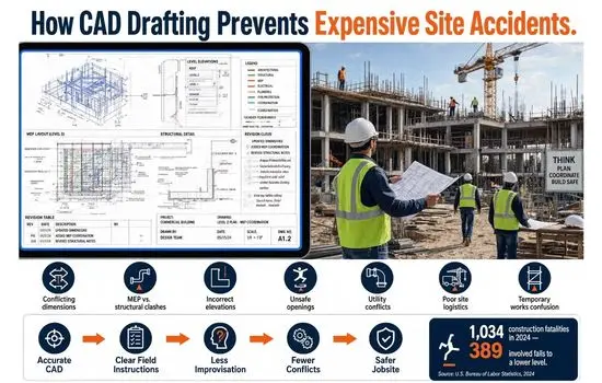
A drafting error is rarely the accident itself. It is the first link in a chain that ends with a struck-by injury, a fall, or a utility strike. According to the Bureau of Labor Statistics, construction recorded 1,034 fatal injuries in 2024, and 389 of those deaths involved a fall to a lower level.
This article explains, with 2024–2026 data, how precise CAD drafting removes the field-level guessing that produces those numbers, and what a buyer should check before hiring a drafting partner.
What Does Precise CAD Drafting Mean on a Jobsite?
Precise CAD drafting means a drawing set that trades can build from without asking a follow-up question. A buildable set removes the interpretation step, and interpretation is where field improvisation, and therefore risk, begins.
A drawing set qualifies as precise when it delivers the following seven elements together, not in isolation.
| Drafting Element | Field Requirement |
| Scale and view setup | Plans, sections, and details match the scale printed on the sheet |
| Dimension verification | No duplicate or conflicting dimensions across sheets |
| Callouts | Each callout points to the correct detail, sheet, and revision |
| Layer discipline | Trades isolate their scope without visual noise from other disciplines |
| Annotation readability | Text height, lineweight, and plot style remain legible on a printed field set |
| Discipline coordination | Architectural, structural, and MEP drawings do not contradict each other |
| Revision control | Issue dates, clouds, and a change log identify a single current set |
How Is CAD Drafting Different From Engineering and BIM?
CAD drafting, stamped engineering, and BIM modeling solve three separate problems, and conflating them is where scope gaps start.
| Discipline | Primary Output | Safety Role |
| CAD drafting | Field-readable plans, sections, details, shop drawings, as-builts | Converts design intent into buildable instructions |
| Engineering | Calculations, code compliance, structural design | Sets the loads and requirements drafting must reflect accurately |
| BIM | Coordinated 3D model across disciplines | Adds clash detection, but disciplined 2D CAD can achieve similar coordination |
Precise CAD drafting does not replace a stamped engineering set. It makes that engineering intent buildable without forcing the field to fill in gaps under time pressure.
What Does a ‘Close Enough’ Drawing Actually Cost?
Design-related errors, including inaccurate drawings and omissions, account for 1 to 9 percent of total project cost, and the Construction Industry Institute puts average direct field rework at roughly 5 percent of project value across a 144-project dataset, rising to a 12.4 percent 90th-percentile on the worst-managed jobs.
Miscommunication alone drives roughly 26 percent of all rework, and inaccurate or missing information drives another 14 to 22 percent, according to industry rework research compiled in 2025.
The drafting issues below show up as “small” in the office and stop being small once a crew is standing in front of them.
- Conflicting dimensions between a plan view and its referenced detail
- Missing tolerances or vague fit-up notes on connections
- Unclear elevations, slopes, or stair geometry
- Wrong datum, benchmark, or reference point carried across sheets
- Outdated details left in a set after a design change
How Does a Drafting Mistake Turn Into a Jobsite Injury?
Serious incidents rarely trace back to one failure. They trace back to a sequence, and CAD drafting sits at the first step of that sequence.
The chain typically runs in this order:
- An unclear drawing including a dimension conflict, missing note, or outdated plan reaches the field
- Incorrect field layout is related to controls, sleeves, or openings getting placed against the wrong reference
- Trade conflicts surface when MEP hits structure, access gets blocked, clearances disappear
- Improvisation under schedule pressure deals with crews cutting, moving, or forcing a fit to stay on schedule
- An unsafe condition appears when overhead work, an unprotected edge, or energized exposure
- The incident occurs when injury, equipment damage, a shutdown, or a schedule delay follows
The improvisation step is where risk concentrates. Once a crew confirms the plan does not match reality, the work still has to get done, and the fastest fix is not always the safest one, particularly around temporary access, trade sequencing, shoring, and field modifications performed at height.
Post-incident documentation gaps compound the damage. Investigators cannot always confirm the latest issued set, OSHA reporting slows down, and insurance claims turn into disputes over who had which revision and when they received it.
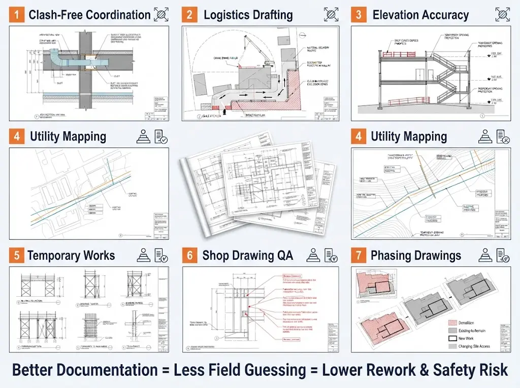
Seven Ways CAD Drafting Prevents Expensive Site Accidents
Each item below functions as a checklist item a GC, subcontractor, owner, or safety manager can request directly from a drafting partner.
1. Does Clash-Free Drafting Reduce Rework and Overhead Cutting?
Coordination is not exclusive to BIM. Disciplined use of overlays, xrefs, and layer standards in 2D CAD prevents the same class of field conflict.
A typical failure sequence: a duct route conflicts with a structural beam, the crew discovers the conflict only after mobilizing, and the result is last-minute cutting and rerouting, often overhead, with tools and debris increasing struck-by and fall exposure.
| Drafting Control | What It Prevents |
| Consistent layer naming across trades | Misread or ignored elements during field layout |
| Xref discipline on a shared base file | Trades referencing outdated or mismatched geometry |
| Overlay-based interference checks | Undetected structure-versus-MEP conflicts |
| Coordinated reflected ceiling plans | Field clashes discovered only after rough-in begins |
2. Can Logistics Drafting Lower Struck-By and Caught-Between Risk?
Struck-by incidents have historically accounted for roughly 11 percent of construction fatalities annually, and many originate outside the building footprint, in staging areas, delivery routes, and crane pick zones that were never clearly drafted.
When a site plan omits a defined material route, forklifts end up sharing a path with foot traffic simply because it is the only workable option, and that daily overlap becomes a recurring struck-by exposure that a dedicated logistics sheet would have prevented.
- Dedicated logistics sheets, separated from general notes
- Crane swing radii, pick zones, and exclusion zones drawn to scale
- Pedestrian routes, barricades, and signage locations called out explicitly
- Phasing drawings that show how access changes week to week
3. How Does Elevation Drafting Reduce Fall Injuries?
Falls remain the leading cause of construction fatalities. BLS data records 389 fatal falls to a lower level out of 1,034 total construction deaths in 2024, and OSHA’s Fall Protection standard has been the single most cited construction regulation for fourteen straight fiscal years.
A large share of fall hazards begin as elevation ambiguity: a spot elevation shown one way on the plan and another way on the detail, a slab depression visible in one view but missing from another, or a protective detail left off an opening that stays exposed longer than intended.
| Where Ambiguity Hides | Drafting Control |
| Roof edges and parapets | Section cuts drawn at every transition, not only at convenient locations |
| Temporary openings | Opening schedules with explicit edge-protection notes |
| Ramps and stairs | Consistent spot elevations and shared datum across all sheets |
| Ladder access points | Access detailed explicitly rather than assumed |
4. Does Accurate Utility Mapping Prevent Strikes and Electrocution?
Underground utility strikes cost the United States roughly 30 billion dollars annually, with the Common Ground Alliance’s 2024 DIRT Report documenting 196,977 reported damage incidents in a single year, and the true national total estimated between 400,000 and 800,000 strikes.
Contractors and developers are found responsible for over 75 percent of utility strike damage, and up to 20 percent of documented incidents trace back to utility records that were missed or marked inaccurately, a category that overlaps directly with outdated or unverified CAD base files.
- Verified base files sourced from current survey data, not an emailed PDF of unknown age
- Utility locate data integrated directly into the CAD background
- Separate existing-versus-new utility layers with a readable legend
- “Field verify” notes used to flag genuine uncertainty, not as a blanket disclaimer
5. How Does Drafting Reduce Temporary Works Risk (Scaffolds, Shoring, Formwork)?
Temporary works fail differently than permanent structures: the risk is immediate and often catastrophic, because a scaffold tie-in or shoring detail that is unclear on paper gets interpreted differently by every crew that touches it.
When a tie-in detail is inconsistent across sheets, assembly varies from crew to crew, and that variance is exactly where stability gets compromised and collapse risk rises.
- Dedicated temporary works sheets whenever the scope is nontrivial
- Standardized details, with outdated versions actively removed from the set
- Direct references to engineer-provided load notes and design requirements
- Revision tracking so a superseded detail cannot linger in a field set
𝗞𝗲𝗲𝗽 𝗖𝗼𝘀𝘁𝗹𝘆 𝗗𝗿𝗮𝗳𝘁𝗶𝗻𝗴 𝗘𝗿𝗿𝗼𝗿𝘀 𝗢𝗳𝗳 𝗧𝗵𝗲 𝗝𝗼𝗯𝘀𝗶𝘁𝗲
Get accurate, coordinated, and field-ready CAD drawings before construction begins. From structural and MEP coordination to shop drawings, revisions, and as-builts, CAD Drafter helps turn design intent into clear construction documentation.
6. Do Accurate Shop Drawings Prevent Installation Accidents?
Shop drawings are where a dimensioning error becomes physical, in steel, rebar, precast, and piping. A misdimensioned steel connection typically gets corrected through field drilling or torching, work that happens at height, under time pressure, with sparks and tools in play.
Engineering and design-related errors account for roughly 70 percent of all construction rework by some industry estimates, and design causes were found responsible for close to 80 percent of cost deviations in a separate analysis, which makes shop drawing accuracy one of the highest-leverage safety and cost controls available.
- Independent QA and peer checks on connection geometry before release
- Dimension chains that avoid redundant or conflicting references
- Tolerance notes wherever fabrication requires them
- A closed RFI loop so unresolved unknowns never reach fabrication
7. Can Phasing Drawings Prevent Sequencing Accidents?
Sequencing hazards appear when trades overlap, access gets blocked, or a protection gets removed before it should. A demo plan missing a “keep in place” note is a common trigger: a guardrail or temporary support gets removed because it looks like part of the demo scope, and incident risk rises immediately.
- Phasing sheets that show what changes, and exactly when
- Demo-versus-new-work layers that are visually distinct on the sheet
- Consistent color and lineweight conventions across every phase
- Explicit “existing to remain” callouts wherever they matter
What Should You Check Before Hiring a CAD Drafting Partner?
Buying CAD support means buying clarity, and clarity is a direct safety input, not a cosmetic one.
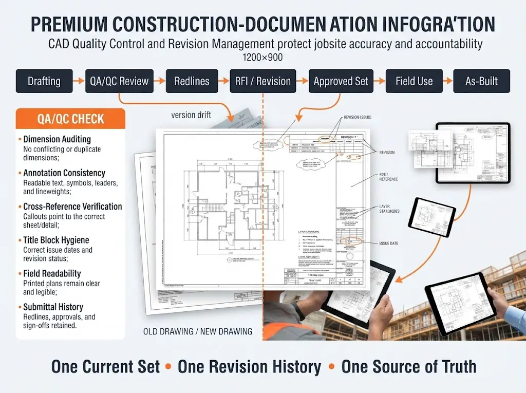
Which QA/QC Habits Actually Matter on a Jobsite?
| QA/QC Area | What to Ask About |
| Dimension auditing | Process for catching duplicate or conflicting dimensions |
| Annotation consistency | Standard text size, leader style, and symbol library |
| Cross-references | How callouts are verified to land on the correct sheet |
| Title block hygiene | Issue dates, revision clouds, and status tracking method |
| Field readability | Plot styles and lineweights tested on an actual printed set |
| Submittal workflow | Redline, markup, and sign-off history retention |
A partner who cannot explain their QA process in plain language is a warning sign worth taking seriously.
How Do You Prevent Version Drift Across a Project?
Version drift happens when more than one file claims to be the “latest” set at the same time, and it is more common than most teams admit.
- Proper xrefs and shared coordinates where applicable
- Formal transmittals for every issued set, not informal email attachments
- A single source of truth with controlled, dated issue points
- Change logs documenting what changed, not only that a change occurred
How Does CAD Drafter Support Safer Construction Documentation?
CAD Drafter provides drafting support that converts sketches, redlines, and mixed field inputs into clean, field-usable construction documentation, which matters most when internal teams are stretched thin or a project is moving on a fast-track schedule.
Common ways an outside drafting team reduces documentation-driven risk:
- Converting architect and engineer redlines into clean, coordinated CAD sheets
- Updating plan sets so field crews never build from an outdated detail
- Translating messy field markups into accurate as-built drawings
- Tightening shop drawing packages through structured revision histories
- Cleaning up existing-condition backgrounds on complex renovation work
For the type of drafting support this covers, see CAD Drafting Services, including scopes such as clash coordination, MEP drafting, and structural steel detailing. For broader positioning, the About page is a quick read.
Which Project Types Need Safety-Driven CAD Support Most?
These project types carry elevated risk when drawings are sloppy, because they combine tight spaces, unknown existing conditions, and overlapping crews.
| Project Type | Primary Risk Driver |
| Tenant improvements | Unknown existing conditions behind finishes |
| Commercial buildouts | Multiple trades working in a compressed timeline |
| Industrial retrofits | Live operations continuing near construction activity |
| Multi-trade interiors | Overlapping MEP and structural scopes in tight ceilings |
| Renovations | Existing conditions that outdated as-builts frequently misrepresent |
| Fast-track schedules | Design and construction proceeding in parallel |
For renovation-heavy scopes specifically, see renovation design services.
What Happens to Documentation After a Jobsite Injury Occurs?
After an injury, the first question is almost always the same: what was supposed to happen, and what actually happened. Poor drawings and unresolved revisions make that question harder to answer.
Accurate CAD drafting paired with disciplined revision control helps clarify several facts quickly:
- Which plan set was the latest issued version at the time of the incident
- What changed, and the exact date it changed
- Whether the field was working from an outdated detail
- Whether a known conflict had been identified and resolved, or ignored
The documentation that most often matters after an incident includes the following records.
| Record Type | Why It Matters |
| Latest issued drawing set | Establishes the plan of record with dates and revision numbers |
| Change orders and approved revisions | Shows what was formally authorized to change |
| RFIs and responses | Documents whether a conflict was flagged before it was built |
| Marked-up field sets and daily reports | Captures real-time field conditions and decisions |
| As-builts | Records what was actually constructed, even if only partially maintained |
| Photo logs and inspection notes | Provides a visual timeline independent of the drawing set |
This is not legal guidance, only practical reality: injured workers and their families typically need to reconstruct what went wrong and who was responsible, and documentation is usually where that reconstruction starts.
Does Location Affect How Fast an Incident Gets Resolved?
In San Diego, CA, projects move on tight schedules and site conditions change daily. When an accident happens, a clean drawing record and revision history shorten the period where nobody can confirm what was actually built or when it changed.
If someone is injured on a jobsite, a local San Diego law firm can review the drawing records, explain the available legal options, and help identify which parties may bear responsibility.
How Do You Add a Safety-First Drafting Step to Preconstruction?
This workflow does not require reorganizing an entire company. It adds one checkpoint focused explicitly on field clarity, not simply on whether the drawings are finished.
| Stage | Core Actions |
| 1. Kickoff | Confirm deliverables, CAD standards, and who owns and updates base files |
| 2. Collect existing conditions | Gather current survey files, utility locates, and site photos; flag confidence level on old as-builts |
| 3. Draft, then run safety QA | Check dimension conflicts, elevation consistency, openings, access routes, and coordination overlays |
| 4. Review loop | Route redlines through PM, superintendent, and trades; log every RFI to resolution |
| 5. Issue control | Date every set, cloud every change, issue formal transmittals, archive prior versions |
| 6. Field feedback and as-builts | Capture markups on a consistent system; update as-builts on a schedule, not only at closeout |
Conclusion
Precise CAD drafting will not stop every jobsite accident, but it removes the ambiguity that starts most accident chains. Coordinated, current, and correctly revisioned drawings cut clash-driven rework, reduce fall and struck-by exposure, prevent utility strikes, and leave a clear record if something still goes wrong. Given that design-related errors alone account for up to 9 percent of project cost, reviewing drawings before crews mobilize, especially on renovation or fast-track work, is one of the cheaper decisions available on any project. It keeps problems on paper, while they are still fixable.

