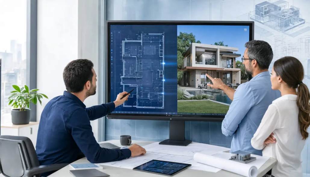
How CAD Drafting and Architectural Visualization Support Better Project Communication
CAD drafting and architectural visualization support project communication by converting complex technical data into clear, visual, and precise models that ensure all project stakeholders stay fully aligned. These digital processes replace manual, unclear methods with a single, reliable source of truth.
By combining structural, mechanical, and architectural specifications within a unified digital framework, they enable teams to confirm every technical detail and plan site logistics well before construction begins.
Primary Categories of CAD and Visualization Services
The professional landscape relies on three core service types that translate concepts into actionable data.
2D Drafting and Documentation
This category centers on producing accurate technical drawings with computer software. Engineers and architects rely on these to specify measurements, tolerances, and assembly guidelines. These two-dimensional depictions are vital for fabricating components, designing construction plans, and adhering to rigorous industry standards for blueprints.
3D Modeling and Parametric Design
Designers build digital solids by defining mathematical parameters and geometric constraints. By adjusting particular values, the entire model updates automatically. This approach enables teams to simulate mechanical movement, inspect for structural clashes, and generate intricate geometries that conventional 2D tools struggle to manage.
Photorealistic Rendering and Visualization
Visualization experts leverage light-simulation engines to generate realistic images from 3D models. By incorporating physical attributes such as reflection, refraction, and surface texture, they transform data into visual assets. It helps the team from 3d architectural rendering company to grasp material characteristics, lighting scenarios, and aesthetic nuances before any physical prototype is created.
BIM (Building Information Modeling)
BIM is a smart method for managing building data across its entire lifecycle. In addition to basic geometry, these models contain details about costs, timelines, and material specifications. It enables architects and contractors to align systems such as plumbing and electrical wiring, helping to avoid expensive mistakes during construction.
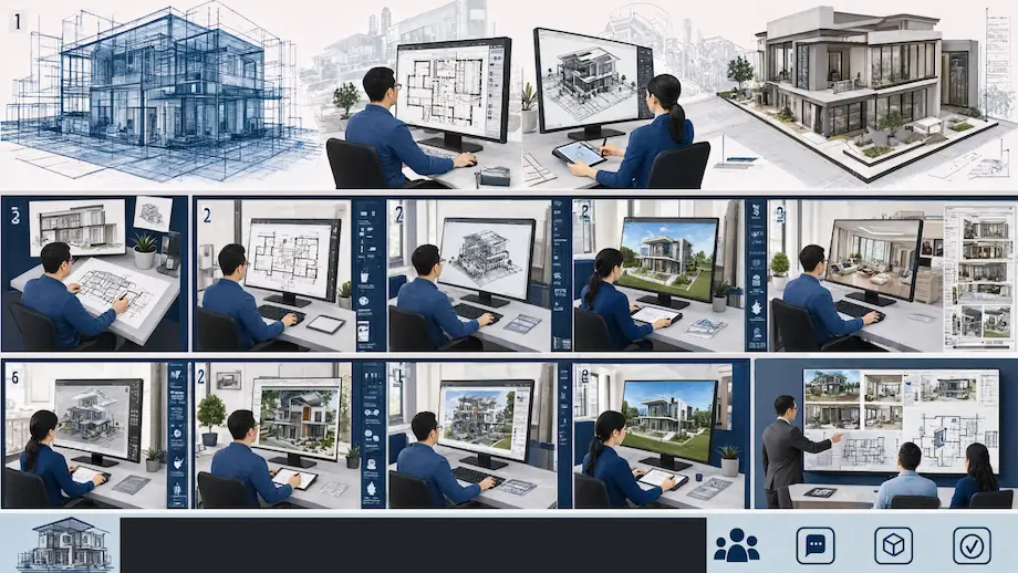
How Different Drafting Disciplines Apply These Same Digital Tools
Different drafting fields employ the same digital tools by adapting core CAD software and BIM platforms to meet their specific technical demands, standards, and coordination requirements throughout a project.
Architectural Drafting
Architects rely on CAD to define a building’s spatial layout, exterior enclosures, and interior circulation. They focus on wall sections, door schedules, and floor plans. These digital models ensure that design aesthetics meet safety codes and local zoning regulations effectively.
Structural Engineering
Structural engineers utilize these tools to model the load-bearing skeleton, including steel frames and concrete footings. They perform stress analysis and calculate material strength. Digital models here emphasize accurate structural stability, gravitational forces, and wind load resilience to ensure safety.
MEP (Mechanical, Electrical, and Plumbing)
MEP professionals use CAD to design and route complex building systems through restricted spaces. They coordinate ductwork, conduit runs, and pipe layouts to avoid physical collisions. This ensures all mechanical services fit within the structural design without interference.
Civil and Site Development
Civil drafters model the land, grading, and site infrastructure using specialized digital terrain tools. They manage water drainage, road alignments, and utility connections. This ensures that the building site functions properly in relation to existing topography and municipal infrastructure.
Each of these disciplines produces drawings that must remain internally consistent with every other trade’s documentation. When all four are coordinated through a shared CAD environment, conflicts that would otherwise surface mid-construction are caught and resolved on screen instead.
Key Strategic Advantages in Digital Construction
Integrating these digital tools provides a distinct competitive edge by increasing design accuracy and reducing financial risk throughout the project lifecycle.
● Design Accuracy
Digital constraints eliminate common scaling errors, ensuring all floor, ceiling, and section plans align with total consistency.
● Field Rework Reduction
Automated clash detection identifies costly physical conflicts between mechanical and structural systems well before they appear on-site.
● Approval Efficiency
High-quality visualizations cut down the time owners need to understand designs, resulting in quicker approvals and fewer change requests.
● Cloud-Based CAD
Gone are the days when drafters had to ask for files to take a look at the recent designs. Cloud-based CAD collaboration helps teams monitor and manage designs seamlessly.
● Compliance Integration
Incorporating code-required details directly into the model accelerates the permit review process and prevents expensive legal delays.
In-House Drafting Compared to Outsourced CAD Conversion
The decision between hiring an in-house drafting team and working with an external provider hinges on factors such as project volume, deadline urgency, and the complexity of the necessary documentation. Both approaches can yield precise outcomes, but the compromises vary in quantifiable aspects.
Capacity flexibility
CAD conversion services allow firms to scale drafting capacity up or down without hiring or layoffs, which matters most during bid season or multi-project overlap
Legacy document recovery
PDF to CAD conversion services convert scanned drawings and static PDFs into editable, layered CAD files that integrate with current BIM workflows
Physical site digitization
3D scan to CAD services transform laser scan point clouds of existing buildings into accurate as-built models for renovation projects
Outsourced providers usually implement standardized quality control checkpoints throughout every project, which can minimize the variation arising from drafting teams with varying levels of expertise operating across different software versions.
Common File Formats and Software Compatibility Challenges
Software compatibility issues often break communication between design teams. If files do not transfer correctly, they can lose key data like layers or dimensions, which leads to confusion and errors.
Version Incompatibilities
Opening or correctly displaying drawings may be blocked if different releases of DWG files are used.
Contact us for accurate drawings and faster project coordination.
Data Loss During Export
Transferring BIM models into neutral formats such as IFC often removes important parametric data and built-in intelligence.
Reduced Quality
Scanning old paper drawings instead of using native conversion leads to disorganized, non-editable files with low line quality.
Proactive Standardization
To prevent technical gaps, teams should agree on a single native file format and a set exchange protocol before starting a project.
Professional Digitization
Specialized services turn paper or raster files into clean, accurate vector drawings that fully maintain your original layer structure.
Methods for Driving Project Communication
Effective project communication depends on centralized digital processes and uniform documentation to guarantee that all stakeholders can access up-to-date, precise information.
1. Common Data Environments
A Common Data Environment acts as a single source of truth for all project-related documents. Teams keep drawings, specifications, and reports in one secure place. This guarantees that every contractor uses the most current version, greatly minimizing construction mistakes and expensive rework.
2. Real-Time Clash Detection
Engineers use automated software to identify physical conflicts between different building systems before construction begins. When a pipe hits a beam in the model, the system flags it. This allows teams to fix issues digitally instead of on-site.
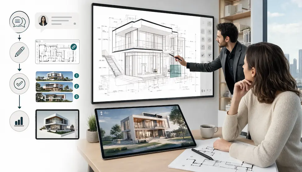
3. Collaborative Markup and Review
Digital review tools allow architects and engineers to leave precise comments directly on CAD drawings. Instead of confusing email chains, team members view feedback in context. This creates a clear audit trail and speeds up the approval process for designs.
4. Integrated Cloud Reporting
Cloud platforms update project progress, costs, and material needs in real time. Managers track material takeoffs and budget impacts as designs evolve. This transparency keeps owners and contractors on the same page regarding the financial health of the project.
| Communication Method | Primary Purpose | Key Benefit |
| Common Data Environments | Centralized file storage | Eliminates version errors |
| Real-Time Clash Detection | Geometric coordination | Prevents site conflicts |
| Collaborative Markup | Design feedback | Speeds up approvals |
| Integrated Cloud Reporting | Real-time project tracking | Ensures budget transparency |
Quality Control Checkpoints Before Drawings Reach the Field
The reliability of a drawing set is directly tied to the strength of the review process behind it. Reputable firms implement organized quality control milestones before any sheet is approved for construction, helping to identify mistakes that might otherwise show up as issues on-site.
Internal peer review
A second drafter, not involved in the original work, reviews dimensions, notes, and cross-references against the project requirements.
Cross-discipline overlay checks
Architectural, structural, and MEP drawings are overlaid and compared to ensure no two systems occupy the same space.
Code compliance verification
Drawings are checked against relevant building codes for egress, accessibility, and fire separation before submission.
Final issue-for-construction sign-off
A senior reviewer confirms that all changes from earlier review rounds have been included before the set is stamped final.
The Role of Shop Drawings in Bridging Design and Fabrication
Shop drawings transform design concepts into precise instructions for construction teams and factories. These documents specify exact measurements and material requirements for each component. Workers rely on them to fabricate parts that fit seamlessly during site assembly.
Avoiding Expensive Mistakes
For materials like steel, timber, and glass, these drawings guarantee that pieces align correctly on the first attempt, preventing costly setbacks.
Emphasis on Structural Elements
Structural steel detailing provides precise data on beam connections, bolt patterns, and welds, ensuring building safety and stability.
Minimizing Human Error
Generating drawings directly from digital models eliminates the need for manual redrafting. This prevents frequent mistakes caused by hand-copying information.
Standardizing Documentation for Construction Readiness
Standardized documentation serves as the final link between the design office and the field, ensuring that intent is captured without any room for ambiguity.
Layering Conventions
Following the National CAD Standard (NCS) allows all consultants to instantly navigate files without requiring custom mapping.
Symbol Consistency
Uniform architectural symbols prevent misinterpretation of plans, ensuring that a door swing or structural connection is correctly understood by every contractor.
Change Management
Implementing a formal RFI (Request for Information) and change-log process keeps the entire team informed of revisions, preventing the use of outdated blueprints on the job site.
Scalable Output
Proper plotting standards ensure that physical prints maintain their dimension-to-scale ratio, which is essential for field measurements.
How Residential and Commercial Projects Apply These Workflows Differently
Residential and commercial projects rely on the same core CAD and BIM technology, yet their distinct scale and regulatory demands call for different workflow priorities.
- Residential projects often focus on swift turnaround times for drafting services and clear visuals, enabling homeowners to assess layouts and material selections before construction starts. In contrast, commercial projects involve larger MEP coordination scopes, strict accessibility code reviews, and multi-tenant phasing, which requires careful discipline-by-discipline sequencing among the drafting team.
- Commercial projects also typically demand more intensive clash detection work upfront, as the density of mechanical and structural systems in multi-story buildings creates far more potential conflict points than a standard single-family home.
Frequently Asked Questions
Is 2D drafting still relevant in a 3D world?
Yes, 2D drafting continues to be the main standard for permit applications and municipal documentation. It delivers the accurate, legally binding records needed for final construction and ongoing facility upkeep.
How do these tools specifically reduce construction costs?
They reduce costs primarily by eliminating mid-construction change orders. Identifying design conflicts in a virtual environment is inexpensive, whereas fixing a physical clash on a job site costs thousands of dollars.
Are VR walkthroughs necessary for every project?
No, VR is best suited for large-scale commercial or high-end residential projects. Smaller designs are usually well served by high-quality static renderings paired with clear, accurate 2D floor plans.
What is the main benefit of BIM over standard 3D modeling?
The main benefit is metadata. Unlike standard 3D models, BIM objects carry data like material costs and fire ratings, which allows for automated cost estimation and interdisciplinary system coordination.
How does visualization help during the permit process?
Visualization helps regulators understand complex site plans and massing quickly. By presenting clear, accurate visual data, you can demonstrate code compliance faster and resolve concerns about zoning or site impact.
Optimizing Your Project Delivery
To achieve the best results, firms must master the integration of these digital tools into a cohesive workflow. Implementing these standardized methods ensures that your communication remains consistent and your projects stay profitable.
Take control of your next project’s success today by standardizing your CAD and visualization processes. Contact our CAD Drafting company to learn how to bridge the gap between technical design and construction reality.