How To Prepare CAD Deliverables For Digital Twin Workflows And IoT Connectivity
Construction firms are increasingly under pressure to deliver smarter, faster, and more connected assets. But far too often, their CAD deliverables fall short of the mark. Despite the global market for digital twin solutions in construction expanding at an estimated 17.3% CAGR, projected to hit nearly $93.5 billion by 2029, many teams still ship drawings that don’t translate into true “live” models.
The problem? Standard CAD outputs (dense DWG files, loosely-defined asset IDs, missing sensor metadata) create hand-off chaos when the goal is a fully interactive digital twin. The geometry may be there, but the data-connectivity bridge is missing.
That’s where this blog comes in. You’ll discover how to prepare CAD deliverables so they aren’t just drawings, but living, breathing inputs for digital twins and IoT connectivity. We’ll walk through project pre-flight decisions, geometry cleanup, metadata tagging, format selection, performance streaming and IoT binding. By the end, you’ll have a clear roadmap to turn CAD deliverables into digital-twin-ready assets.
Why CAD Deliverables Need To Change For Digital Twins
Walk onto almost any construction site today, and you’ll find drawings everywhere. These are in the form of PDFs, DWGs, and 3D models stacked on shared drives. They’re detailed, but they stop at the surface. They describe shape, not behavior. When a project moves into a digital twin environment, that limitation becomes obvious fast.
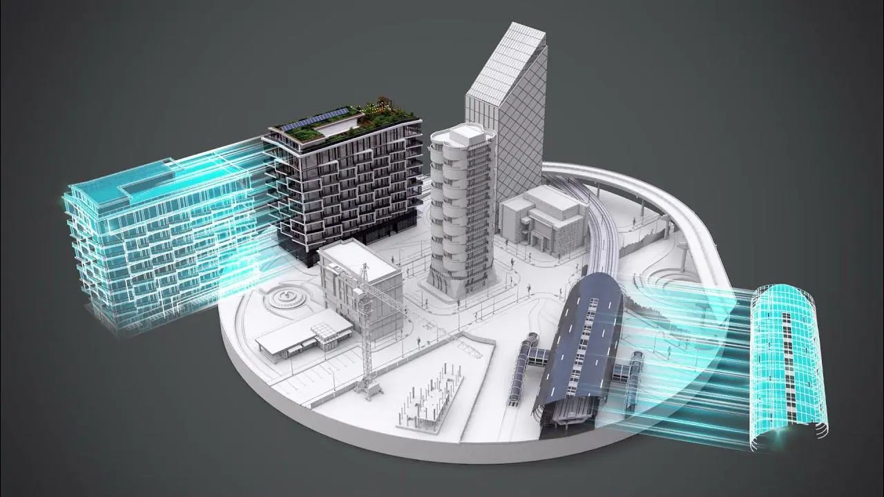
A digital twin isn’t a static replica. It’s a living version of the built space that learns, reacts, and stores information from sensors and systems. The old way of delivering CAD files doesn’t give it what it needs to live. It’s like trying to run a smart building with blueprints alone.
Change is no longer optional, and here’s why:
- CAD deliverables must hold data, not just geometry. Every beam, pipe, and panel needs tags and metadata so the system knows what it’s looking at.
- IoT devices depend on consistent identifiers. Without proper IDs in your CAD data, sensors can’t talk to the model.
- Massive models slow everything down. Files need to be optimized for streaming so viewers can handle large structures without freezing.
- Owners expect long-term value. A twin isn’t just a design tool! It’s used for operations, maintenance, and predictive insights.
- Teams work differently now. Engineers, facility managers, and data analysts all need to see the same model in real time, not pass around separate versions.
Traditional CAD handoffs end when construction ends. Digital twins keep going. Preparing deliverables with that future in mind is how you keep your work relevant in an industry that’s moving toward real-time intelligence.
Preflight: Project Decisions to Make Before Exporting CAD
Before exporting a single file, pause and think about what happens next. The model you’re building won’t stay trapped in CAD forever. Someone will stream it, link it to sensors, or open it in a twin viewer that reacts to real-world data. If the groundwork isn’t right, every later step becomes harder.
A small mistake here can ripple through an entire digital twin workflow, and fixing it later costs time, money, and sometimes credibility. The idea is simple: get your model to speak the same language as the tools and devices it will meet.
Use this quick preflight list before exporting:
- Coordinate system: Decide which reference your model follows. Keep all geometry consistent. Even minor misalignment can cause sensors to map to space.
- Level of Detail: Don’t guess. Plan the level of detail based on what the model will do. Lower LOD for early coordination, higher for as-built accuracy.
- Viewer target: Know the destination. Web viewers, game engines, and cloud twin platforms all interpret data differently.
- Format choice: DWG, IFC, RVT, glTF, 3D Tiles; each serves a purpose. Choose based on the end user and system requirements.
- IoT scope: Identify which assets will carry live data. Tag those now with stable IDs and clean metadata.
There’s no glamour in this step, but it’s the one that decides whether your CAD deliverables glide smoothly into a digital twin or crash on import.

Geometry & Model Cleanup: Best Practices
Messy geometry might pass unnoticed in a design file, but once the model enters a digital twin environment, every extra line and hidden layer becomes a problem. Large DWG or RVT files choke viewers, delay data sync, and inflate storage costs. Clean geometry is not about making things pretty but keeping the model functional and fast when it goes online.
Strip Out What Doesn’t Belong
Start with the junk. Remove temporary construction lines, internal reference geometry, and layers that never need to appear in a live twin. Delete scaffolding, placeholders, and hidden backup groups. They clutter the export and confuse automated conversion tools. The goal is to leave only what a digital twin needs to represent. These are the parts of the building that exist, move, or gather data.
Simplify and Merge
Many families, blocks, or nested elements carry far more detail than required. Replace high-polygon parts with simpler versions. Merge repeating objects when possible, especially furniture, piping segments, or light fixtures. The fewer separate meshes you export, the better the performance in a browser or 3D viewer.
Repair the Geometry
Tiny errors can cause big problems when converting to glTF or 3D Tiles. Check for overlapping faces, open edges, inverted normals, and stray points. Run the model through an audit or cleanup utility before exporting. Even a few fixes here can prevent the endless “missing face” issues that show up later in the viewer.
Tools Worth Knowing
Autodesk’s native cleanup tools handle basic checks, but for heavier work, try Blender or MeshLab. Both can reduce polygons and verify normals quickly. Navisworks is useful for clash detection and combining multiple discipline models before export. Each tool has its quirks; test a small area before committing to full-scale cleanup.
Metadata & Asset Tagging: The Bridge to IoT
A clean model means nothing if it doesn’t know what it’s showing. You can have the most detailed geometry, but if your digital twin can’t tell one pump from another, it’s blind. Metadata is what fixes that. It gives each object its own name, history, and job. That’s what allows a digital twin to connect with IoT data and act like a real system instead of a static model.
Start with Real IDs
Every object in your CAD or BIM file needs an ID that makes sense. Not a random code, not a placeholder. Something stable. A tag that follows the part from drawing to field installation. For example, a fan coil could be tagged MECH_FCU_045. The same ID will appear on a sensor, a dashboard, and a maintenance record.
If you use Revit, add these tags as shared parameters. In AutoCAD, put them in extended data fields. Stick with one method across the whole project. Once the tag exists, never change it. That tag becomes the thread that connects the digital object to the physical one.
Make the Digital Match the Physical
When sensors or control devices go online, they come with their own identifiers. It could be an OPC UA node, an MQTT topic, or a label in a controller. Map those identifiers to your CAD IDs in a spreadsheet. Keep it simple. One row per asset.
| AssetID | OPC_UA_Node | MQTT_Topic | Sensor_Type | Commissioned_Date |
| MECH_FCU_045 | ns=3;s=FanSpeed_045 | site1/fcu045/speed | Temperature | 2024-07-10 |
| ELEC_LGT_102 | ns=4;s=Switch102 | site1/light102/state | OnOff | 2024-07-15 |
That small sheet becomes the key that links your CAD model to real readings. Once imported into a twin platform, the data starts flowing. The temperature sensor on that fan coil isn’t just a number anymore; it updates a live 3D element in real time.
Put Information Inside the Model
Don’t rely only on external files. Store essential data directly in the model. IFC and Revit both allow rich property sets. Add what matters. It can be the manufacturer, model, serial number, commissioning date, warranty, and maintenance cycle. If the component has an IoT device, include the address or data endpoint.
Keep it focused. The goal is to have enough information to identify and connect, not to turn your CAD file into a database dump. Too much data can slow everything down and make exports messy.
Tools That Help
Revit schedules are good for managing and exporting parameters. Dynamo scripts can automate asset tagging. AutoCAD users can write simple routines to push object names into CSV format. Mesh-based exports like glTF or USDZ can carry extra data through JSON sidecar files. Always test a small model before sending the full project out. Some formats strip metadata if not configured correctly.
Keep It Up to Date
Once the project is running, things change. Equipment gets replaced, sensors fail, IDs drift. The model needs to stay aligned with the site. Treat your asset registry like a logbook — update it when something changes in the field. The digital twin should never fall behind the real building.
Metadata and tagging don’t look impressive when you’re doing them. It’s quiet work. But they decide whether your twin behaves like a real system or just sits there as a frozen 3D model. When done right, every tag is a voice. Together, they make the building speak.
Contact CAD Drafter For CAD to Digital Twin Services
Coordinate Systems, Georeferencing & Units
Every model exists in some kind of space. If your CAD file doesn’t align with reality, nothing else works. Decide whether you’re using a local grid, state plane, UTM, or another standard. Once chosen, stick to it for all project files. Mixing coordinate systems is a common cause of objects floating in the wrong place or appearing misaligned when streamed online.
Units matter too. Meters, millimeters, feet: pick one and keep it consistent. Some viewers, like Cesium or AWS TwinMaker, assume meters by default. If your model is in millimeters without conversion, it may appear huge or tiny in the virtual environment. Small mistakes here lead to big headaches later.
|
Pro Tip |
| Sometimes models have internal origin points that don’t match the real-world location. Attach metadata or tags to track these offsets. |
GIS overlays are sensitive to these settings. A simple misalignment can make a building float above the site or sit inside a road. Streaming platforms rely on correct CRS and units for proper rendering and interaction. Correct georeferencing ensures that digital twins match sensor feeds, point clouds, and real-world coordinates.
In short, decide your coordinate system, lock in your units, document any offsets, and embed them in metadata. Do this early. It prevents countless hours of troubleshooting later when your model refuses to line up with reality. Georeferencing may feel tedious, but it’s the foundation of a functional digital twin.
Tools & Automation: Recommended Tools, Converters, and Cloud Services
Moving a CAD model into a digital twin is not just a matter of “save as.” There are several tools that handle different parts of the process, from cleaning geometry to converting formats and connecting to live data. Each has its purpose.
Revit + Revit API
Revit stores the core design. The API allows you to automate tagging objects, generating schedules, or exporting multiple views. It’s useful if you want consistent outputs without doing everything by hand.
Navisworks
Navisworks combines models from different disciplines. It can detect clashes and create a single, unified model. This step is often necessary before streaming or sending files to the cloud.
FME
FME can transform files from IFC or Revit into glTF, 3D Tiles, or other formats. Metadata, coordinate systems, and layer structures can be carried over. It’s especially useful for repeating conversions across multiple projects.
Cesium Ion
Cesium Ion takes models and prepares them for web streaming. It handles LOD, textures, and basic metadata. Large models become manageable and viewable in browsers without freezing.
Autodesk Forge
Forge can read Revit, DWG, and other CAD files, then convert them or extract data via API. It works when you want to build custom viewers or pipelines for cloud platforms.
Blender
Blender is a free tool for editing geometry, reducing polygons, or checking mesh integrity. It’s handy before exporting to glTF for visualization.
MeshLab
MeshLab is lightweight. It’s used for cleaning meshes, repairing normals, and minor adjustments.
AWS IoT TwinMaker
TwinMaker connects geometry to IoT sensors. It updates objects in real time based on telemetry. It’s not for geometry cleanup, but for turning a model into a working twin.
A typical workflow might start with Revit, pass through FME or Blender for cleaning, then stream via Cesium Ion, with TwinMaker connecting live data. No single tool does everything. Testing each step on a sample model is important.
File Formats: Which To Export, When, and Why
Choosing a file format matters. The wrong format can break a workflow, lose data, or make your model unusable. CAD files do more than hold geometry. They carry metadata, schedules, and object relationships. If you export carelessly, you lose that information.
BIM and Authoring Files
RVT, IFC, and DWG are the main options for engineering and design. Revit files keep parametric detail and schedules. IFC is open and works across platforms but may miss some custom Revit elements. DWG is older. It handles 2D drawings well but doesn’t store deep BIM data.
Use RVT if the next step involves editing in another Revit project. Use IFC for collaboration across teams using different software. Keep DWG for drawings that need to be shared for permits, construction, or reference.
Visualization and Streaming
Web viewers and cloud twins need lightweight formats. glTF is small, handles textures, and works in real time. 3D Tiles splits large models into chunks for streaming. B3DM and 3DX tiles wrap geometry and metadata for specific platforms like AWS TwinMaker and Cesium.
A typical workflow looks like this: start with Revit or IFC, convert to glTF or 3D Tiles, then optimize with a tool like FME, Forge, or Cesium Ion. Test a small portion before converting the whole model. Large models without optimization can freeze viewers or crash applications.
Point Clouds
Point clouds store scanned data in LAS or LAZ. They provide the real-world geometry of a site. Before linking them to your model, clean and register them. Match segments to objects with bounding boxes or reference layers. Raw point clouds are heavy and difficult to stream if left unprocessed.
When to Keep DWG and When to Convert
DWG is useful for 2D deliverables. Keep it for documentation, permits, or as-built reference. Don’t try to stream it directly in a web viewer. Curate the geometry you want to display and convert that into glTF or 3D Tiles. Keep originals for record-keeping.
Export Decision Matrix
| Intended Use | Format | Tools | Notes |
| Editing and review | RVT | Revit, Navisworks | Full parametric data, editable |
| Collaboration | IFC | Revit, FME, Solibri | Interoperable, preserves metadata |
| Web visualization | glTF / 3D Tiles | Forge, Cesium Ion, Blender | Optimized for streaming |
| Scanned survey | LAS / LAZ | Recap, CloudCompare, Cyclone | Align and clean before linking |
| Construction documentation | DWG | AutoCAD, Navisworks | Layers, annotations, legal reference |
Pick a format based on what happens next. RVT and IFC hold intelligence. glTF and 3D Tiles make it visible and interactive. DWG stores documentation. Point clouds add reality. Plan each export. Test small portions. Preserve metadata. Keep the originals. This approach prevents errors and keeps the digital twin accurate and usable.
Mapping Models to Live Data: IoT Integration Patterns
A CAD model by itself doesn’t respond to the world. It sits in 3D space. To make it a digital twin, it has to connect to real devices and sensors. That connection turns static geometry into something that updates, reacts, and reflects actual conditions.
Building an Asset Registry
Start with a simple table linking every CAD object to a sensor or controller. This is the “asset registry.” Each entry should include the object’s AssetID, model identifier, sensor type, and data endpoint.
Example:
| AssetID | Model GUID | Telemetry Endpoint | Sensor Type |
| MECH_FCU_045 | 1234-abcd | mqtt://site1/fcu045/speed | Temperature |
| ELEC_LGT_102 | 5678-efgh | opc.tcp://site1/light102/state | Switch |
The registry makes it clear which object in the model receives which data. When a sensor updates, the twin knows exactly where to apply the value. This is critical on projects with many devices. Without it, data becomes disconnected and unreliable.
Choosing Messaging Protocols
Sensors use different methods to send data. MQTT works well for simple, frequent updates. Each device publishes to a topic, and the twin subscribes to it. Keep topic names consistent. For example:
site1/buildingA/fcu045/speed
A sample payload:
| Sampling Code |
| {
“timestamp”: “2025-11-12T10:32:00Z”, “value”: 22.5, “unit”: “C” } |
Industrial equipment often uses OPC UA. Data is organized in nodes. Each CAD object is mapped to a node. The registry ensures the node path matches the model ID.
Putting It Together
Imagine a fan coil in a building. Its AssetID in Revit is linked to a temperature sensor’s MQTT topic. Every reading updates the twin. At the same time, a boiler controlled via OPC UA sends flow and pressure readings. The twin visualizes both in real time.
Key Points
- Keep the asset registry up to date. If a sensor changes, update the mapping.
- Use a consistent naming system. It avoids confusion and errors.
- Decide on MQTT or OPC UA depending on the sensor type.
- Embed metadata in the CAD model where possible. It makes mapping simpler.
- Test small sections before applying it to the full model.
This approach makes a twin that reflects reality. It stops being just a 3D file and starts acting as a live system. Data flows in, visuals update, and the model becomes meaningful.
FAQ
What CAD format is best for a construction digital twin?
RVT or IFC works for design fidelity and metadata. Use glTF or 3D Tiles when you need streaming performance in web or cloud viewers. Choose based on your workflow and intended platform.
How do I connect a BIM object to an MQTT topic?
Assign a unique AssetID in your model, map it to the topic in a CSV or database, and subscribe via your digital twin platform. Example: mqtt://site1/fcu045/speed.
How can I reduce model size for web streaming?
Remove temporary layers, simplify high-poly families, merge repeated objects, and use formats like glTF or 3D Tiles. Check normals and LODs to keep the model functional without excess geometry.
What is the difference between DWG, IFC, and RVT for twins?
DWG is for 2D drawings, IFC is open and interoperable, RVT keeps full parametric data. Choose DWG for documentation, IFC for collaboration, and RVT for detailed editing.
How do I assign consistent coordinate systems?
Pick a common CRS, keep units consistent, and document offsets in metadata. Ensure that GIS overlays, Cesium, or AWS TwinMaker display geometry in the correct location.
What’s a good way to organize IoT telemetry mapping?
Use an asset registry linking AssetID → Model GUID → Sensor endpoint. Track MQTT topics or OPC UA nodes. Keep updates in sync with CAD/BIM changes.
Which tools help convert CAD to glTF?
FME, Blender, Cesium Ion, and Autodesk Forge are reliable options. Revit exports can feed into these tools. Clean geometry and check metadata before conversion.
How do I handle point cloud data in a digital twin?
Use LAS/LAZ formats, clean and register segments, then link them to model objects via bounding boxes or metadata. Avoid streaming raw point clouds directly.
Can I automate metadata export from Revit?
Yes. Shared parameters, schedules, and Revit API scripts can extract asset IDs, manufacturer data, commissioning dates, and sensor information to CSV or JSON for twin integration.
What’s the best way to maintain a digital twin over time?
Keep asset registry and model metadata updated. When devices are replaced or settings change, reflect those updates in the model. Metadata accuracy keeps the twin aligned with the physical building.
Conclusion
Turning CAD models into functional digital twins takes more than exporting files. Geometry, metadata, IoT mapping, and proper formats all matter. Don’t let your designs sit idle. CAD Drafter can help you launch a pilot project, convert drawings to live twins, or deliver Scan-to-BIM models ready for IoT integration. Reach out today and see how your CAD data can come alive, stream seamlessly, and connect to the real world.