7 Red Flags to Look for in AI-Generated Generative Designs Before Sending to the CNC Mill
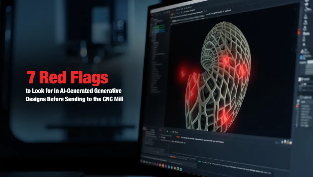
AI-generated CAD models are undeniably stunning. They look like alien bones, bionic lattices, or something pulled straight out of a high-end sci-fi concept art book. The software runs thousands of iterations in the cloud, stripping away material where it isn’t needed and maximizing strength-to-weight ratios.
Then you send that file to the machine shop. The machinist takes one look at it, laughs, and hands it right back.
Why? Because mathematically flawless does not mean physically machinable. If you don’t aggressively audit your AI-generated CAD models before hitting export, you are risking broken carbide end mills, blown-out spindles, and entirely scrapped billets of expensive material.
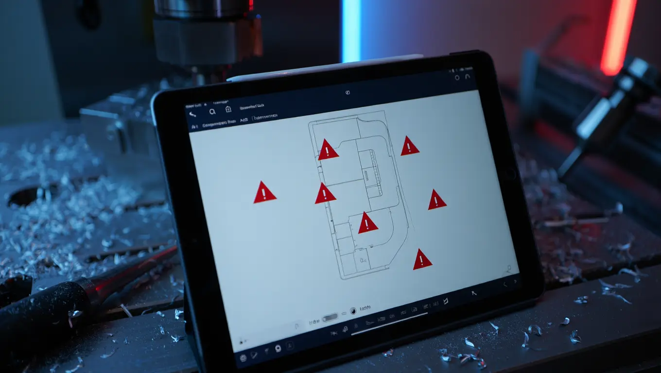
Before generating any G-code, you need to dissect the model. Here is a deep technical breakdown of the most critical red flags hiding inside your generative designs.
Red Flag #1: “Ghost Geometry” and Unreachable Cavities
Generative AI operates in a limitless digital void. It fundamentally does not care how a piece of spinning carbide is going to physically enter a pocket.
Solid Isotropic Material with Penalization (SIMP)
Algorithms utilizing Solid Isotropic Material with Penalization (SIMP) run intense stress simulations and aggressively penalize heavy areas. The AI hollows out the inside of the part, leaving behind complex internal webbings, cavernous undercuts, and bizarre overlapping artifacts.
In the drafting and auditing world, these un-millable artifacts are known as ghost geometry.
If the design features a hollow internal cavity accessible only by a tiny entry hole, how exactly is the end mill supposed to clear that out? A CNC mill is not a 3D printer. It cannot build material up layer by layer out of thin air. It has to plunge, contour, and physically evacuate chips out of the cutting zone. If a cavity has an overhang angle that blocks spindle access, a standard 3-axis mill physically cannot manufacture it. Even a 5-axis machine hits a hard wall based on tool stick-out lengths and holder clearance.
● The Deep Pocket Trap
AI frequently creates deep, narrow channels to shave off a few ounces of mass. But cutting a pocket that is ten times deeper than the tool’s diameter invites massive tool deflection, brutal chatter, and an abysmal surface finish.
● The Undercut Illusion
Generative models constantly design interlocking shapes or heavy overhangs. Without a specialized lollipop cutter or a highly complex, multi-setup 5-axis indexing routine, these features are functionally impossible to mill.
AI Additive Bias vs. CNC Subtractive Reality
| Design Feature | AI Expectation (Additive Focus) | CNC Reality (Subtractive Constraint) |
| Internal Cavities | Easily printed layer-by-layer. | Physically blocked. Solid tooling cannot reach inside. |
| Deep Channels | Perfect mass reduction strategy. | Heavy tool deflection; requires custom extended-reach tooling. |
| Complex Overhangs | Solved with temporary breakaway supports. | Requires 5-axis simultaneous milling and high-clearance tool holders. |
| Material Yield | 100% efficient. Only uses what is required. | Terrible. 80-90% scrap rates are common when carving organic shapes from square billets. |
Red Flag #2: Missing Safety Codes and Token-Minimization Bias
Let’s talk about the actual code generation. The industry is seeing a massive push toward using AI plugins and Large Language Models (LLMs) to optimize G-code directly for faster cycle times.
Do not trust this blindly. Recent manufacturing data highlights a terrifying reality: AI code generators suffer from token-minimization bias.
To an AI, the goal is to shorten the code block and make the machining process mathematically faster. It looks at a sequence of G-code, identifies patterns, and starts slashing. The core issue here is that AI lacks a semantic understanding of real-world manufacturing safety protocols. It will actively strip out critical safety features because it views them as “redundant text.”
-
Erased Tool Length Compensation (G43/H Codes)
AI optimization tools have been caught deleting G43 commands to save space. This is catastrophic. Without G43, the machine controller does not know how long the cutting tool is. It will blindly drive a two-inch end mill straight through your aluminum billet and into the cast iron machine table at full rapid traverse speed.
-
Missing Return to Safe Position (G28)
Generative AI often deletes the G28 command at the end of a cycle. Instead of raising the spindle out of the way to a safe tool-change position, the machine might try to index the carousel while the tool is still buried deep inside a metal pocket.
-
Pocket Milling Omissions
AI has a nasty habit of deleting entire pocket-milling routines if it incorrectly calculates that a contour pass was “close enough.” It optimizes for raw speed by completely ignoring the heavy material removal phase, attempting to force a fragile finishing tool to plunge directly through solid steel.
You must manually audit the code. If you rely on AI to generate your toolpaths without a line-by-line verification in simulation software, you are flying blind.
Red Flag #3: Perfect 90-Degree Internal Corners (The Fillet Failure)
This is a classic rookie mistake. Surprisingly, multi-million-dollar CAD automation workflows and AI algorithms make it constantly.
AI models optimizing for stress distribution love sharp, clearly defined geometry where loads transfer efficiently. They will routinely spit out designs featuring mathematically perfect, razor-sharp 90-degree internal corners.
Look at a CNC end mill. It is a cylinder. It is physically impossible for a spinning, round cylinder to cut a sharp inside corner. It will always leave a radius equal to the tool’s diameter.
If the AI design requires a sharp internal corner so a mating component can slide into place, the machinist is forced to intervene. They have to stop everything and do one of three things:
- Broach the corner (slow and expensive).
- Use Electrical Discharge Machining (EDM) (very slow and massively expensive).
- Modify the CAD model to include “dog-bone” reliefs so the mating part can actually seat properly.
Red Flag #4: The Workholding Nightmare (Erased Datum Surfaces)
To cut a piece of metal, you have to be able to hold the piece of metal. It sounds ridiculously simple, but generative AI frequently treats the laws of physics as suggestions.
When a machinist sets up a job, they rely on Datums. These are flat, parallel surfaces used to clamp the billet securely in a vise. These planes are the North Star for the machine; they are used to set zero coordinates and ensure the part doesn’t move an inch during aggressive cutting.
The Melted Candle Problem
Generative algorithms treat material like an enemy, stripping away every ounce of metal not carrying a structural load. The result? A part that looks like a melted candle:
- Organic Curves with swooping bionic arms that offer no grip.
- Zero Flat Surfaces, which means there would be nothing for the hardened steel jaws of a vise to bite into.
- The Impossible Clamp is another melted candle indication. You can’t clamp a marble in a vise and expect it to stay still under the pressure of a 12,000 RPM spindle.
The Manufacturing Bottleneck
If you send a completely organic shape to the mill, you aren’t just sending a file; you’re sending a headache. The shop is forced to:
- Machining a second set of “negative” jaws just to hold your part.
- Adding extra material to the bottom of your part just to grip it, which must be cut off later.
- Intentionally leaving “holding tabs” that require a secondary manual operation to remove.
You might save 20% on part weight, but you’ve just increased setup time and labor costs by 400%.
Material Yield vs. Economic Disaster
Subtractive manufacturing lives and dies by Material Yield. It is the ratio of the final part volume to the original raw billet.
| Metric | Traditional Design | Blind AI Optimization |
| Billet Requirement | Sized close to the final part. | Massively oversized to fit sweeping curves. |
| Scrap Rate | 20% – 30% (Standard) | 80% – 90% (Common in organic AI parts). |
| Vibration Risk | Low (Rigid geometry). | High (Thin arms act like tuning forks). |
| Surface Finish | Smooth, linear paths. | “Stuttering” marks from complex interpolation. |
Harmonic Chatter
AI stress simulations focus on how the part behaves after it’s bolted into a machine. They rarely simulate the violence of the machining process itself.
- Thin-Wall Resonance: As the mill carves away support, those bionic arms become susceptible to extreme chatter.
- Lateral Pressure: A part that survives a 1,000-lb static load might snap in half when a 1/2-inch end mill applies 50 lbs of lateral cutting force.
- The Controller Stutter: When AI forces a machine to interpolate along thousands of tiny, variable-radius curves, the machine controller can “lag.” This creates microscopic dwell marks, ruining the finish and requiring hours of manual polishing.
Red Flag #5: The Un-Threadable Blind Hole (The Fastener Failure)
Let’s talk about how parts actually fit together in the real world. You need bolts, screws, and threaded inserts to assemble complex mechanisms. Generative design algorithms absolutely understand the location of a mechanical load, but they have zero respect for the physical mechanics of tapping a hole.
When an AI generates a structural boss meant to hold a tapped hole, its instinct is to aggressively minimize the surrounding material to save weight. Worse, it frequently places these threaded holes deep inside recessed pockets or at bizarre, multi-axis compound angles.
When you are machining a blind hole (a hole that does not completely pierce through the material), the metal chips being cut need somewhere to evacuate. If the CAD automation scripts and generative AI hasn’t left adequate depth for chip clearance below the final thread requirement, the tap will pack full of aluminum or steel chips. The moment that happens, the tap binds and snaps off flush with the surface. You now have a piece of hardened high-speed steel permanently embedded in your expensive part.
The Easy Fix
You must audit every single fastener location. Ensure there is enough surrounding “meat” (wall thickness) to handle the torque of a bolt without cracking the bionic structure. Furthermore, if a hole requires threads, it needs to be accessible by a straight, rigid toolholder. If the AI placed a tapped hole beneath an overhanging bionic arch, you will never get a tap straight into it. You will be forced to use costly, specialized right-angle milling heads, destroying your profit margins.
Red Flag #6: Asymmetrical Thermal Expansion Traps
Metals are not static. They move, twist, and warp when exposed to heat. AI algorithms almost exclusively run static load simulations at room temperature. They absolutely do not simulate the aggressive, localized thermal shock of a 3-inch shell mill hogging out aerospace material at 12,000 RPM.
Generative designs are notorious for mixing massive, chunky structural nodes with extremely thin, delicate, web-like connecting arms. To a computer, this is the perfect distribution of material. On a CNC machine, this extreme variance in wall thickness is a thermal time bomb.
As the cutter aggressively removes the bulk material from the heavy sections, friction pumps massive amounts of heat into the part. The thin, bionic webbing heats up and expands rapidly, while the thicker, chunky sections stay relatively cool. This uneven expansion introduces massive internal stress into the billet.
When the machinist finally unclamps the vise to remove the finished part, that trapped stress releases. The part instantly bows like a banana. A component that measured perfectly flat inside the machine is suddenly warped out of tolerance the second it hits the inspection table.
| An Expert’s Insight On How To Spot It |
| Look for extreme transitions in your CAD tree. If a heavy, solid mounting block suddenly transitions into a 0.050-inch-thick sweeping arm, you have a thermal trap. You must manually add transitional fillets, increase the thickness of the thin webs, or mandate a slow, multi-stage stress-relief machining process (which drastically increases cycle times). |
Red Flag #7: The 5-Axis Spindle Collision Illusion
There is a dangerous myth in modern manufacturing: “If it’s too complex for 3-axis, just throw it on the 5-axis.” Generative AI relies heavily on this myth. It designs incredibly convoluted, undercut geometry under the assumption that a 5-axis machine can simply tilt the tool to reach it.
But AI algorithms suffer from a massive blind spot: they assume the cutting tool and the spindle head are infinitely small. They aren’t. A modern 5-axis spindle is a massive, bulky block of cast iron, coolant lines, and sensors.
The tool might technically be able to reach an internal bionic pocket, but the giant metal spindle holding that tool will violently smash into the side of the part trying to get there. In the machining world, this is known as a spindle collision, and it can cause tens of thousands of dollars in damage in a fraction of a second.
If an AI generates a tight, deep, bowl-like structure and expects the tool to tilt 45 degrees to reach the bottom corners, you must run that exact geometry through highly accurate machine kinematics simulation software (like Vericut or Mastercam). You aren’t just checking if the tool fits; you are checking if the entire machine fits inside the AI’s complex geometry.
Real-World Application: Machining Heavy-Duty Solar Mounting Hardware
Let’s step away from aerospace and look at a practical, heavy-duty industrial example. Imagine you are engineering a custom, high-angle roof mounting bracket for a heavy off-grid solar array or a massive battery bank system. These components face immense structural challenges.
You run the environmental parameters through an AI generative design platform. The algorithm optimizes for wind resistance and weight, spitting out a beautiful, organic, bionic truss system. It looks like a spider web made of metal. It technically saves 35% in weight compared to a traditional blocky bracket.
But you aren’t 3D printing this bracket. You need to machine it out of weather-resistant extruded aluminum billets to maintain structural integrity.
The AI Failures in this Scenario:
-
The Fastener Nightmare
The AI placed the lag-bolt mounting holes underneath a sweeping bionic arch to protect them from rain. A standard drill cannot reach them. The installer on the roof won’t be able to get an impact driver onto the bolt head either. The part is functionally useless.
-
The Extrusion Waste
To machine this swooping, spider-web bracket, you have to start with a massive, rectangular block of aluminum. You will end up machining 85% of that expensive block directly into the scrap bin. The raw material cost completely obliterates any savings from the part being “lighter.”
-
Vibration and Chatter
Solar mounts require long, rigid arms. The AI hollowed these arms out into thin, tuning-fork-like structures. When the CNC machine attempts to cut them, the vibration will shatter the cutting tools and leave a terrible surface finish that will aggressively accelerate corrosion when exposed to the elements.
The Human Override Is Necessary
A seasoned CAD drafter and CNC programmer would take that AI concept and heavily modify it. They would straighten the bionic curves into machinable planes. They would open up the fastener pockets for easy tool access. They would thicken the tuning-fork arms to prevent machining chatter. They would hybridize the AI’s brilliant structural logic with the harsh, undeniable laws of subtractive manufacturing.
Get expert CAD & BIM solutions today!
The Ultimate CAD Audit Workflow
To consistently bypass these red flags, you need a standardized auditing protocol. Never send raw generative geometry to the shop floor. Treat the AI’s output as a “rough sketch,” not a final blueprint. Implement this three-step audit before generating a single line of G-code.
Step 1: The Bounding Box and Yield Test
Instantly draw a standard rectangular bounding box around your AI-generated model. This represents the raw billet of material you will need to purchase.
Calculate the volume of the box versus the volume of the part. If your material yield is less than 20% (meaning you are throwing away 80% of the metal as chips), hit the brakes. Ask yourself: Can this organic shape be broken down into two simpler, flat parts that bolt together? Redesigning a single complex bionic node into an interlocking assembly can drop your raw material costs by half.
Step 2: The Spherical Tool Proxy Test
This is how you hunt for “hidden ghost geometry.” In your CAD software, create a sphere that matches the diameter of your standard roughing end mill (e.g., a 0.500-inch sphere). Now, try to manually drag that sphere through every single pocket, channel, and internal cavity of the AI model.
If the sphere gets stuck (if a channel narrows to 0.400 inches, or if an overhang blocks the sphere from entering from the top) you have found an un-machinable feature. You must manually open up those pathways or completely erase that internal cavity.
Step 3: The Datum Lock Verification
Inspect the bottom of the model. Does it have at least two perfectly flat, parallel surfaces? If the AI has melted the bottom of the part into an organic curve, you cannot hold it in a standard machine vise. You must manually extrude a flat base, or design temporary “holding tabs” onto the sides of the part. These tabs will allow the vise to grip the metal securely while the complex top geometry is carved away, and can be snipped off manually later.
If you want to know more about auditing AI-generated CAD models, check our detailed guide with streamlined steps. [How To Audit AI Generated CAD Designs]
AI vs. Human Machinist: The Decision Matrix
| Feature | AI Generative Output | Human Auditing Action Required |
| Thin Bionic Webs | Maximizes weight-to-strength ratio. | Thicken webs by 15% to prevent vibration chatter and tool breakage. |
| Sharp Internal Corners | Ideal for simulated load transfer. | Insert dog-bone reliefs or strict tool-matched radiuses. |
| Blind Internal Cavities | Shaves off unnecessary center mass. | Delete completely. Solid metal must remain if a tool cannot reach it. |
| Compound Tapped Holes | Placed purely for structural necessity. | Re-orient to standard X/Y/Z planes for straight-line tapping access. |
Conclusion
Ultimately, the goal of using AI in manufacturing is to increase profitability. But if you blindly trust algorithms biased toward additive manufacturing, you will achieve the exact opposite.
Every extra hour your CNC machine spends trying to carefully navigate a fragile, bionic web is an hour of lost production. Every custom fixture you have to design to hold an oddly shaped, organic part eats directly into your profit margin. Generative design is an incredibly powerful brainstorming tool. It will show you load paths and material efficiencies that a human brain would never naturally conceive.
But it takes a human to actually build it. So, audit aggressively, design for your specific tooling, and always remember: just because a computer can draw it, doesn’t mean a machine can cut it. If you want CAD Drafters with automation expertise to work on your next project, give us a call and get a quote for free.
Frequently Asked Questions (FAQs)
How does thermal expansion ruin AI-generated parts?
AI models feature massive variances in wall thickness. During heavy CNC milling, friction heats the metal. Thin AI-generated bionic webs expand and warp drastically compared to thicker sections, causing the final part to bow out of tolerance when unclamped.
Can thread milling solve AI fastener issues?
Sometimes. Thread milling requires less force than rigid tapping and evacuates chips better, making it safer for blind holes. However, if the AI placed the hole at a compound angle underneath an overhang, even a thread mill cannot physically reach it.
What is a spindle collision in 5-axis machining?
AI often designs deep cavities, assuming a cutting tool can tilt infinitely. However, it ignores the massive physical bulk of the machine’s spindle. When the machine tilts to reach the cavity, the cast-iron spindle crashes into the part, causing catastrophic damage.
Why shouldn’t I use a 1/8-inch end mill for deep AI pockets?
Operating a tiny tool in a deep pocket creates a massive aspect ratio. The lateral cutting forces will cause a 1/8-inch end mill to instantly deflect, chatter violently, and snap. Standard milling requires keeping depth-to-diameter ratios below 5:1 whenever possible.
How do I check for un-machinable “ghost geometry”?
Perform a spherical proxy test in your CAD software. Create a solid sphere matching your smallest tool diameter and drag it through the model’s cavities. If the sphere cannot pass through, a real end mill cannot either. You must widen the channel.