Prompt Engineering for CAD: 10 Useful Prompts + Complete Guide
Imagine trying to describe a complex planetary gear assembly over the phone to someone who has never seen one. That is exactly what talking to early generative AI felt like for mechanical designers. You asked for a load-bearing bracket; you received a lumpy, melted plastic donut.
But the technology has quietly matured. We have moved past generating pretty, unusable 3D meshes. Today, AI can write the exact Python scripts needed to generate parametric solid bodies in FreeCAD, Fusion 360, and Blender. It can draft constraint logic. It can troubleshoot broken assemblies.
Prompt engineering for Computer-Aided Design (CAD) is no longer a parlor trick. It is a core technical competency.
If you are still manually clicking through menus to create bolt circles or calculate chamfer depths, you are losing time. This guide breaks down exactly how to talk to machines so they output manufacturable, mathematically sound geometry.
The Complete Guide: How AI Actually Understands CAD
Before we get to the prompts, you need to understand how large language models (LLMs) interpret physical space.
AI does not have spatial awareness. It doesn’t “see” the 3D object you are imagining. Instead, it understands relationships, mathematics, and code. If you ask an AI to “draw a cool car,” it will fail. If you ask it to “write a Python script for Autodesk Fusion 360 that generates a parametric cylinder with a diameter of 50mm, filleted top edge of 2mm, and a concentric 10mm through-hole,” it will succeed flawlessly.
To get professional-grade results, you must shift your mindset from visual description to mathematical instruction.
The Anatomy of a Perfect CAD Prompt
To stop getting garbage outputs, every CAD prompt you write needs four distinct pillars:
- The Medium: Are you asking for a Python script for a specific software API (FreeCAD, Fusion 360, Rhino/Grasshopper)? Or are you asking for OpenSCAD code? You must declare this immediately.
- Base Geometry & Origin: Always define where the object starts. State the coordinate planes (XY, XZ, YZ) and the origin point (0,0,0).
- Parametric Variables: Never hardcode numbers if you can avoid it. Tell the AI to set up variables for length, width, and thickness so you can change them later.
- Constraints: AI models will leave sketches unconstrained unless you explicitly tell them to lock down the geometry. Specify concentricity, parallel lines, and tangent arcs.
Workflow: Scripting vs. Native Text-to-3D
Right now, native text-to-3D engines (like Luma or Point-E) generate polygons and meshes. Meshes are great for video games. They are completely useless for CNC machining or precise 3D printing because they lack solid boundary representations (BREP).
Therefore, the most powerful way to use AI in CAD today is Code-Based Generation. You prompt the AI (like ChatGPT or Claude) to write OpenSCAD scripts or Python API scripts for your specific CAD software. You then paste that code into your software’s console, hit run, and watch the solid body generate automatically.
The prompts below are designed primarily around this professional, code-driven CAD automation workflow.
10 Useful Prompts for CAD
Here are the first five high-level prompts. They are engineered to be highly specific, variable-driven, and ready to be adapted to your specific software stack.
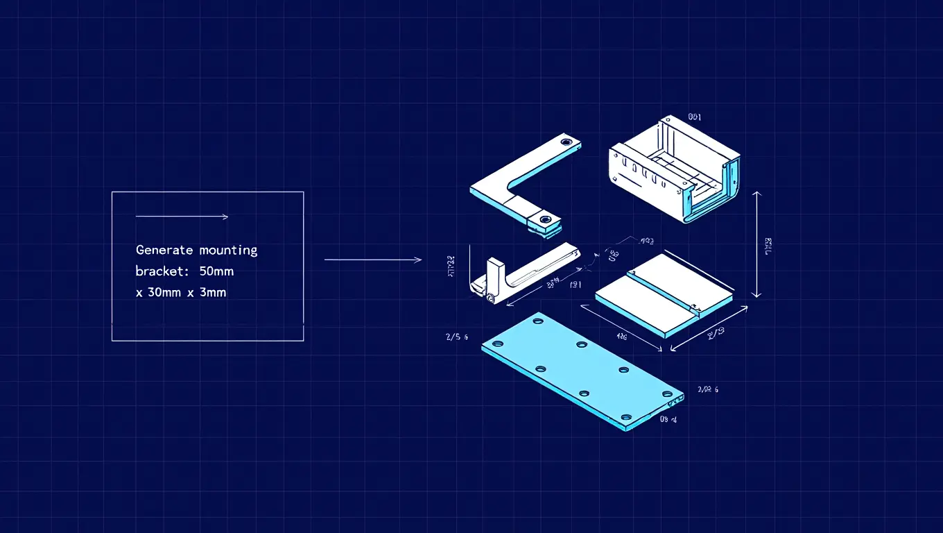
Prompt 1: The Parametric Base Component Generator
This prompt is your workhorse. Use this when you need to generate standard brackets, enclosures, or mounting plates without spending 20 minutes sketching and dimensioning
The Prompt |
| “Act as an expert mechanical engineer and programmer specializing in [Insert Software, e.g., FreeCAD Python API / OpenSCAD]. I need a script to generate a parametric L-bracket.
Please establish the following variables at the very top of the script so I can easily change them later:
The script must create the solid base body. On the vertical face of the L-bracket, place a single centered through-hole based on the Hole_Diameter variable. On the horizontal face, place two symmetrical through-holes spaced evenly along the depth. Ensure the script generates a valid, fully closed solid body. Add comments explaining the coordinate math used to center the holes.” |
Why it works:
It forces the AI to declare variables at the top of the script. If the bracket ends up being too small, you don’t have to read the code, you just change the Bracket_Height variable from 50 to 80 and run it again.
Prompt 2: The Tedious Math Automator (Bolt Circles & Arrays)
Calculating the exact X and Y coordinates for holes in a circular pattern is annoying. Let the AI do the trigonometry and write the array logic.
The Prompt |
| “I am designing a custom flange in [Insert CAD Software] and need a Python script to generate a circular pattern of holes (a bolt hole circle).
Create a script that defines a solid cylinder (Flange_Diameter = 120mm, Flange_Thickness = 15mm). Then, write a function that subtracts a polar array of holes from this cylinder. Parameters for the array:
Use sine and cosine math to calculate the exact X and Y coordinates for the center of each hole, looping through the Number_of_Holes to create the cuts. Print the calculated coordinates to the console before executing the cuts so I can verify the math.” |
Why it works:
Instead of relying on the CAD software’s built-in circular pattern tool (which sometimes breaks when parent features update), this prompt hardcodes the trigonometry. Asking the AI to print the coordinates first gives you an immediate quality control check.
Prompt 3: Design for Additive Manufacturing (DfAM) Analyzer
Sometimes you don’t need code; you need an expert consultant. If you are designing parts for 3D printing (FDM or SLA), you need to account for overhangs, warping, and layer adhesion.
The Prompt |
| “I am designing a custom [Insert Part, e.g., drone motor mount] that will be 3D printed out of [Insert Material, e.g., PETG] using an FDM printer. The part will experience continuous heavy vibration and radial loads.
Act as an expert in Design for Additive Manufacturing. Ask me 5 specific questions about my current geometry, wall thicknesses, and print orientation. Once I answer, provide a detailed step-by-step checklist on how I should modify my CAD model to eliminate the need for support structures, prevent thermal warping during printing, and maximize tensile strength along the Z-axis. Do not give generic advice; tailor it strictly to continuous vibration and FDM mechanics.” |
Why it works:
This is a reverse-prompt. By forcing the AI to ask you questions first, you prevent it from spitting out generic Wikipedia-style advice. It narrows its focus down to your specific mechanical constraints.
Prompt 4: The Generative Design Constraint Framer
If you are using generative design tools (like Fusion 360’s Generative Design workspace) to lightweight a part, the hardest step is defining your preserve regions and obstacle regions. AI can help you map this out logically.
The Prompt |
| “I am setting up a generative design study to create a lightweight, topology-optimized [Insert Part, e.g., suspension control arm] for a [Insert Context, e.g., off-road rover].
I need to define my load cases, preserve geometry, and obstacle geometry. Based on standard automotive engineering principles for a double-wishbone setup, generate a precise list of:
|
Why it works:
Generative design solves problems based strictly on the boundary conditions you set. If you forget to model an obstacle volume for a bolt head, the AI will put metal exactly where your wrench needs to go. This prompt acts as a safety checklist to ensure your simulation setup is flawless.
Prompt 5: Legacy 2D to 3D Translation Logic
Many engineers sit on piles of old 2D technical drawings or PDF blueprints that need to be modernized into 3D parametric models. AI can map out the order of operations for you.
The Prompt |
| “I am looking at a legacy 2D engineering drawing of a [Insert Object, e.g., cast iron valve body]. I need to model this from scratch in 3D using solid modeling best practices.
I will describe the three views (Top, Front, Right) and the main dimensions. I want you to act as a master CAD instructor. Do not write code. Instead, give me a step-by-step Order of Operations tree for the feature tree. Tell me exactly which plane to start sketching on, which base feature to extrude or revolve first to minimize complex cuts later, and exactly when in the timeline I should apply my fillets and drafts to avoid breaking the model.” |
Why it works:
CAD models fail because of poor feature tree management. Applying fillets too early or sketching on faces instead of origin planes leads to broken models. This prompt utilizes the AI’s logical sequencing abilities to give you an optimal, unbreakable modeling strategy before you even click your mouse.
Get expert CAD & BIM solutions today
Prompt 6: The API Error Troubleshooter
When your Python script fails in Fusion 360, FreeCAD, or Blender, the console logs are notoriously cryptic. An error reading BRepBuilderAPI_MakeFace Failed tells you absolutely nothing about why it failed. AI excels at translating machine-code panic into plain-English diagnostics.
The Prompt |
| “I am writing a Python script for the [Insert Software] API to extrude a multi-profile sketch, but the console keeps throwing the following error: [Paste Error Code/Message].
Below is the snippet of code generating the failure: [Paste Code Block] Act as a senior CAD software developer. Analyze this code block specifically for topological errors, unclosed sketch loops, or intersecting boundary representations. Do not just rewrite the code. First, explain exactly why the geometry kernel is rejecting my logic. Then, rewrite the snippet to include debugging print statements so I can identify exactly which coordinate is causing the failure before providing the corrected fix.” |
Why it works:
Instead of begging the AI to magically “fix it,” you are forcing it to act as a diagnostic tool. By requesting print statements, you create a feedback loop. If the CAD automation script fails again, you now have the exact coordinates of the broken vertex to feed back into the prompt.
Prompt 7: The Tolerance and Fit Advisor
Clearance, transition, interference. Getting these fits wrong on a computer screen means absolutely nothing. Getting them wrong on the machine floor means thousands of dollars in scrapped parts. You can use LLMs to navigate standard ISO tolerance tables and calculate thermal expansion deltas.
The Prompt |
| “I am designing a shaft-and-bore assembly for a high-speed electric motor in CAD. The solid shaft is exactly 15mm in diameter and will be machined from 316L Stainless Steel. The bore is housed in a 6061-T6 Aluminum block. The operating temperature of this unit will peak at 180°C.
Act as a precision manufacturing engineer. Recommend the exact ISO tolerance classes (e.g., H7/g6) required to maintain a slight interference fit at room temperature while entirely avoiding seizing at peak operating temperature due to the distinct thermal expansion coefficients of the two metals. Provide the exact upper and lower dimension limits in millimeters that I need to input into my CAD model.” |
Why it works:
This prompt bridges the gap between digital modeling and mechanical physics. It forces the AI to account for real-world environmental factors (heat) and material science (coefficients of expansion) before giving you a hard CAD dimension.
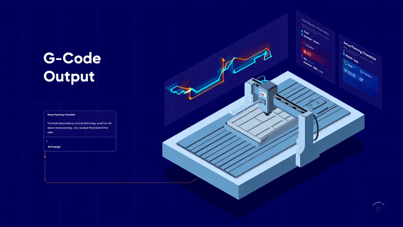
Prompt 8: The CAM/G-Code Pre-Processor Strategy
Transitioning a beautiful 3D model into the CAM (Computer-Aided Manufacturing) workspace ruins a lot of good days. A model that looks perfect might be completely un-machinable due to tool radius limitations or poor setup planning.
The Prompt |
| “I have finished designing a 2.5D aluminum enclosure plate in my CAD software. I am preparing to move into the CAM workspace to program the toolpaths for a standard 3-axis CNC mill.
The part features 35mm deep 90-degree internal corners, a series of M4 tapped blind holes, and a large central pocket. Provide a strict CAM toolpath strategy. Outline the ideal sequence of operations (e.g., Facing, Adaptive Clearing, Contour Finishing, Spot Drilling). Explicitly highlight the internal corner issue; suggest the maximum endmill diameter I can use, and tell me exactly how to model a ‘dogbone’ corner relief in my CAD workspace before I generate the G-code.” |
Why it works:
This anticipates manufacturing failures before you leave the design space. By asking for an operational sequence, you get a blueprint for your CAM feature tree.
Prompt 9: The Kinematic Assembly Map
Mates, joints, and constraints in complex assemblies frequently cause cyclical solver errors. If you over-constrain a moving mechanism, the whole file freezes. AI can map out your joint hierarchy to prevent this.
The Prompt |
| “I am assembling a mechanical 4-bar linkage mechanism in [Insert CAD Software]. I have the four rigid links modeled independently. I need a logical map of assembly constraints to make it simulate motion correctly.
Act as a kinematic design expert. Walk me through the exact sequence of mates to apply between Link 1 (the grounded base), Link 2 (the driving crank), Link 3 (the floating coupler), and Link 4 (the rocker). Detail which specific degrees of freedom (DOF) must be locked or left free at each joint. Finally, warn me about which specific redundant constraint usually causes a solver failure in this type of planar linkage.” |
Why it works:
It prevents the dreaded “assembly is over-defined” error. It utilizes the AI’s understanding of kinematic theory to give you an instruction manual for your mouse clicks.
Prompt 10: The Syntax Translator (Software to Software)
Switching software ecosystems is painful. If you have legacy code or a script written for one program, you can use AI to seamlessly translate that geometric logic into another API.
The Prompt |
| “I have the following procedural 3D modeling script written in OpenSCAD: [Paste Script]
I am migrating my workflow. Act as an expert CAD API developer. Translate this exact logic into a working Python script for the FreeCAD Part Workbench API. Ensure that the Boolean subtraction operations in the original OpenSCAD script are correctly mapped to FreeCAD’s specific Boolean cutting methods. Add brief inline comments explaining the equivalent functions you used, so I can learn the new syntax.” |
Why it works: It automates tedious language migration without losing the underlying dimensional accuracy. It also acts as an incredible personalized tutor for learning a new CAD API.
Advanced Section: The Art of the Iterative CAD Prompt
Writing the first prompt is just the beginning. One of the biggest CAD drafting mistakes designers make when using AI for CAD is treating the LLM like a vending machine: you put a prompt in, and you expect a perfect model to pop out.
When generating complex geometry via code, the AI will make mistakes. It might generate a cylinder on the X-axis when you wanted it on the Z-axis. It might fail to execute a Boolean cut because the tool body perfectly touches the target body face instead of intersecting it (a classic zero-thickness manifold error).
To master this, you must learn Iterative Debugging. When the geometry fails, do not throw the script away. Instead, describe the physical failure back to the AI.
Example of an Iterative Correction Prompt |
| “Your previous script successfully generated the base cube and the cutting cylinder. However, the boolean subtraction operation failed to execute. In this software API, the tool body must physically extend beyond the boundaries of the target body to cut properly. Currently, they share a coincident face. Adjust the Z-axis length of the cutting cylinder to extend 5mm past the top and bottom faces of the base cube, and rewrite the boolean command.” |
Notice the tone? It is direct, diagnostic, and rooted in the rules of 3D modeling engines. You are acting as the eyes; the AI is acting as the hands. You tell it what it cannot see, and it will rewrite the math to fix it.
Overcoming Hallucinations in the 3D Space
AI models are text-prediction engines. Sometimes, they will confidently invent a function in a CAD API that simply does not exist. For example, it might try to use a command like CreatePerfectGear() in Python, assuming the software has a built-in macro for it.
When you get an “Unknown Function” error, immediately challenge the AI’s assumption:
“The script failed on line 42. You used the function Fusion360.ExtrudeToFace(). The API documentation indicates this function does not exist. Please check your assumptions, review the official API methods for extrusion, and provide an alternative way to accomplish this using standard boundary representation logic.”
By holding the AI accountable to the actual API documentation, you force it out of its hallucinatory shortcut and back into rigid, mathematical programming.
Conclusion
Prompt engineering for CAD is not about finding a magic sentence that instantly designs a jet engine. It is about learning how to translate spatial reasoning, physical constraints, and manufacturing realities into logic that a machine can process. The designers who master this workflow (who learn how to generate complex parametric scripts, debug assemblies with AI, and map out CAM strategies via text) will drastically outpace those relying solely on manual sketching. Stop clicking endlessly. Start scripting intelligently.
Frequently Asked Questions (FAQs)
Can AI directly output native CAD files like SLDPRT or F3D?
Currently, AI cannot directly generate proprietary native files like SLDPRT or F3D. It excels at outputting programmatic scripts, such as Python or OpenSCAD, which you execute inside the software to instantly generate fully parametric models.
Is prompt engineering for CAD difficult to learn for beginners?
It requires shifting your mindset from visual drafting to logical instruction. If you understand basic coordinate geometry and the order of operations in 3D modeling, writing highly effective AI prompts becomes an intuitive and fast process.
Can AI models automatically fix broken assembly constraints?
AI cannot directly reach into your software to fix constraints. However, by describing the error code and mating logic, AI can diagnose the conflict and suggest the exact redundant mate you must delete to resolve it.
Will AI eventually replace mechanical designers and drafters entirely?
AI accelerates the tedious aspects of drafting and mathematical calculations, but it lacks physical intuition. Engineers who embrace AI scripting will undoubtedly replace those who refuse to adapt, acting as a powerful multiplier for human creativity.