Line Weights and Annotation Standards | Why They Matter in CAD
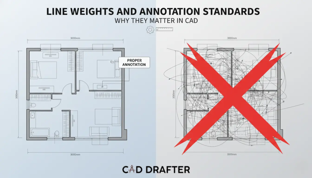
In the world of architecture, engineering, and construction (AEC), a CAD drawing is more than just a digital file, it is a legal contract, a technical instruction manual, and a historical record. Yet, one of the most frequent causes of on-site errors isn’t a math mistake; it’s a communication failure. When a contractor cannot distinguish between a load-bearing wall and a decorative partition because the line weights are identical, the integrity of the project is at risk.
According to a study by the Journal of Construction Engineering and Management, design-related rework accounts for up to 15% of total project costs. A significant portion of this rework is attributed to ambiguity in documentation. Mastering line weights and annotation standards is the primary defense against this ambiguity. This 3,000-word guide explores why these standards are the heartbeat of professional CAD and how to implement them effectively.
The Psychology of Visual Hierarchy
Why do we use different line weights? It isn’t for aesthetics; it’s for cognitive load management. The human brain processes visual information by prioritizing contrast. In a complex floor plan, if every line has a thickness of 0.25mm, the viewer’s eye has no anchor.
Primary-Secondary-Tertiary Framework
To make a drawing readable, we apply a hierarchy. It mirrors the physical importance of the objects. Here are the components of its framework.
- Primary (Heavy): Structural elements like exterior walls or columns. These cut lines represent the most permanent parts of the building.
- Secondary (Medium): Interior partitions, doors, windows, and cabinetry.
- Tertiary (Thin/Light): Hatching, textures, dimensions, and hidden lines. These provide context but should not compete with the actual geometry.
Line Weight Standards: The Technical Specifications
In the transition from hand-drafting to CAD, the industry adopted standardized thickness scales. While different regions use different systems (ISO vs. ANSI), the principles remain consistent.
The ISO 128 Standard
The International Organization for Standardization (ISO) provides a rigorous framework for line types. In a professional CAD environment, line weights are usually assigned by Layer or Object Color (CTB CAD files in AutoCAD).
| Line Type | Recommended Weight (mm) | Common Application |
| Extra Bold | 0.50 – 0.70 | Border frames, title block outlines, section cut lines. |
| Bold | 0.35 – 0.40 | Structural walls, concrete outlines, major equipment. |
| Medium | 0.25 | Interior walls, doors, stairs, furniture outlines. |
| Fine | 0.13 – 0.18 | Dimensions, leaders, centerlines, hatching, hidden lines. |
The Scale Factor
It is necessary to use optimum scale according to site plan. Using the same line weights for a 1:10 detail drawing and a 1:100 site plan is not ideal.
- Small Scale: Line weights must be thinner to avoid blooming.
- Large Scale: Line weights must be thicker to provide enough contrast for high-detail components.
Annotation Standards: The Voice of the Drawing
If lines are the skeleton of a CAD drawing, annotations are the voice. Annotations include dimensions, text notes, labels, and symbols. Without standardized annotations, a drawing is just a shape; it has no scale or context.
Text Height and Readability
A professional CAD standard mandates that text must be legible when printed. The industry standard for Minimum Plotted Text Height is generally 2.5mm (3/32).
- General Notes:5mm
- Sub-headings:5mm
- Sheet Titles:0mm – 7.0mm
The Power of Leads and Terminators
How you point to an object matters. Annotation leaders (the lines connecting text to an object) should never cross each other.
- Arrowheads: Used for pointing to physical edges or surfaces.
- Dots: Often used for pointing to areas or volumes.
- Consistency: Mixing different arrowhead styles on a single sheet creates a perception of unorganized data, leading to a loss of trust from the contractor.
Dimensions: The Geometry of Truth
Dimensioning is where most CAD drawings fail. Over-dimensioning creates clutter, while under-dimensioning leads to guesswork on the job site.
The Chain vs. Baseline Logic
- Chain Dimensioning: Placing dimensions end-to-end. While efficient, tolerance stack-up can occur, where small errors in each segment add up to a massive error at the end.
- Baseline Dimensioning: All dimensions start from a single datum or reference point. This is the gold standard for high-precision engineering (CNC) and structural foundations.
Accurate Statistic: The Cost of Dimensioning Errors
A survey by the National Institute of Standards and Technology (NIST) found that interoperability issues and documentation errors cost the U.S. capital facilities industry an estimated $15.8 billion per year. A significant portion of this is attributed to manual transcription of dimensions that were poorly annotated in the original CAD files.
Line Types and Their Symbolic Meanings
Just like CAD drawing formats, every line style communicates a specific physical reality. Misusing a line type is equivalent to a typo in a legal document.
- Continuous Lines: They represent visible edges.
- Dashed Lines: Hidden lines exhibit edges that are behind or beneath the current view.
- Center Lines: These represent the axis of symmetry. Also, they highlight the center of a circular hole.
- Phantom Lines: Represent alternate positions of a moving part or an adjacent object for context.
Standardizing Symbols and Callouts
In a globalized industry, symbols must be universal. Using a non-standard symbol for a light switch or a structural bolt can lead to catastrophic installation errors.
The Importance of the Legend
No matter how standard your symbols are, every set of CAD drawings must include a Symbol Legend. This ensures that even if a new contractor is hired halfway through a project, they can interpret the digital language of the lead designer.
Section and Detail Callouts
The cross-referencing system is the most complex part of annotation.
- Targeting: A section bubble on Sheet A-101 must point to the specific drawing on Sheet A-301.
- Standardization: Using Dynamic Blocks in modern CAD ensures that if the sheet number changes, the callout updates automatically. This reduces Coordination Errors, which account for nearly 30% of all RFIs (Requests for Information) during construction.
Contact CAD Drafter to know more about annotation standards and line weights
The Economic Impact of Standardized Drafting
Why should a firm invest 100+ hours into creating a CAD Standards Manual? The return on investment (ROI) is found in Reduced Lifecycle Costs.
| Metric | Without Standards | With CAD Standards |
| Drafting Speed | Variable (reinventing the wheel) | 25% Faster (using templates) |
| QA/QC Time | High (manual checking) | Low (automated standards audit) |
| On-site Errors | Frequent (misinterpretation) | Rare (clear communication) |
| BIM Integration | Impossible (fragmented data) | Seamless (structured data) |
Digital Execution: Mastering Plot Styles (CTB vs. STB)
What shows up on screen isn’t what comes out of the printer by default. That handoff (from model space to paper or PDF) is governed by Plot Style Tables. Miss this, and firm-wide standards fall apart fast. Get it right, and everything lines up.
Color-Dependent Plot Styles (CTB)
CTB is the old workhorse. Line weight is tied directly to color. Draw something in red, it prints thin. Switch to cyan, it prints heavy. The rule lives in the color table, not the object.
Pros: Easy for experienced drafters to read at a glance. Mistakes jump out visually.
Cons: True color becomes off-limits. Push past 255 line weight needs, and the system starts to strain.
Named Plot Styles (STB)
STB takes a different route. Line weight comes from a named style, not a color. Heavy, Thin, Hidden, those labels get assigned directly to layers or objects, regardless of how they look on screen.
Pros: Color can be used freely for organization without affecting print results. Much better suited for dense, multi-discipline sets.
Cons: It demands discipline. Templates must be tight, and standards must be enforced.
Annotative Scaling: Solving the Text Size Headache
Text size used to be a constant headache. A detail at 1:10 needed one text height. A plan at 1:100 needed another. The workaround was duplication.
The Power of Annotative Objects
Annotative scaling removed that friction. A single text or dimension knows how tall it should plot. Set it to 2.5 mm, mark it annotative, and the software handles the rest. Change the viewport scale, and the text adjusts automatically. Same object. Different views. No rework.
- The Golden Rule: Never scale your text manually in Model Space. Use the Annotation Scale toggle to ensure that regardless of the viewport, your notes remain perfectly consistent at 2.5mm on the printed page.
Advanced Dimensioning Standards: Clarity Over Clutter
Effective dimensioning is an art of restraint. Over-dimensioning is just as dangerous as under-dimensioning because it creates a busy drawing where critical information is lost.
The Gap and Extension Standard
Professional drawings should never have dimension lines touching the object.
- Offset from Origin: There should be a 1.5mm to 2mm gap between the object and the start of the extension line.
- Extension Beyond Line: The extension line should continue roughly 1.5mm past the arrowhead.
These small gaps prevent the eye from confusing a dimension line with a physical wall or edge.
Tolerance and Precision Levels
A common amateur mistake is setting the dimension precision too high.
- Construction: Rounding to the nearest 1mm or 1/8 is sufficient.
- Mechanical/CNC: Precision may need to go to 0.001mm.
- The Risk: If you provide a dimension of 1500.342mm for a wooden stud wall, the contractor will ignore. That’s because such precision is impossible in carpentry. This undermines the credibility of the entire drawing set.
Annotation in the Era of BIM (ISO 19650)
As the industry moves toward Building Information Modeling (BIM), the way we annotate is changing. We are moving from dumb text to Data-Driven Tags.
From Text to Tags
In a world with BIM execution plans like Revit or Archicad, labels aren’t typed in by hand. You don’t write 300 mm concrete wall anymore. You place a tag, and that tag pulls its information directly from the 3D element behind it.
- The Benefit:
Change the wall thickness once in the model, and the update ripples everywhere. Sheets, details, callouts (hundreds of them) adjust automatically without a single manual edit.
- The Standard:
This only works when everyone follows the same rules. The BIM Execution Plan (BEP) must clearly define tag names and parameters. So, Structural, MEP, and Architectural models all speak the same language.
| Component | Traditional CAD Annotation | BIM Data-Driven Tag |
| Door Schedule | Manual text entry in a table | Automated schedule based on Door ID |
| Room Names | Individual MTEXT objects | Room objects with area/volume metadata |
| Revisions | Manual Cloud and Delta | Automated revision tracking per sheet |
The CAD Standards Manual
To maintain premium quality, you cannot rely on memory. You must document your standards in a CAD Standards Manual. This document should be the first thing a new hire reads.
Essential Sections of a Standards Manual:
- Layer Naming Convention
- File Naming Convention
- Standard Font Styles
- Hatch Patterns
Quality Control: The Redline and Audit Process
Even with the best standards, errors happen. A professional drafting workflow must include a formal QA/QC phase.
The Three-Step Audit:
- Automated Standards Check: Use the STANDARDS command in CAD to automatically find and fix layers that don’t match the firm’s template.
- Visual Black and White Check: View the drawing in Grayscale or Monochrome to ensure that line weights provide enough contrast. If the drawing looks like a grey blob, the hierarchy is failing.
- The Peer Review: Have a drafter from a different project look at your drawings for 10 minutes. If they can’t tell what the primary structural system is, the annotation is insufficient.

Common Pitfalls and How to Avoid Them
| Pitfall | Consequence | Solution |
| Overlapping Text | Unreadable notes on-site. | Use Background Masks on text objects to wipe out hatching behind them. |
| Exploding Blocks | Destroys data integrity and standards. | Lock layers and use Dynamic Blocks instead of manual drafting. |
| Inconsistent Scales | Incorrect measurements by contractors. | Always include a Graphic Scale Bar so measurements can be verified if printed at the wrong size. |
| Missing Xrefs | Parts of the drawing disappear. | Use Relative Paths for External References (Xrefs) to ensure links don’t break when files move. |
Layer Management and Naming Conventions (AIA vs. ISO 13567)
A drawing’s visual clarity is only as good as its underlying architecture. In CAD, this architecture is defined by the Layering Standard. Without a strict naming convention, a drawing becomes a digital graveyard where information is buried under Layer1, Layer2, or Temp.
The AIA CAD Layer Guidelines
The American Institute of Architects (AIA) standard is widely used in North America. It follows a four-field format:
- Discipline Code: (e.g., A for Architecture, S for Structural, M for Mechanical).
- Major Group: (e.g., WALL for walls, DOOR for doors).
- Minor Group: (e.g., FULL for full-height, PRTN for partitions).
- Status: (e.g., NEWW for new work, EXST for existing).
Example: A-WALL-FULL-NEWW tells any user exactly what they are looking at without opening a legend.
The ISO 13567 Framework
For international projects, the ISO standard uses a numerical field system. While more complex to memorize, it allows for better computer-aided filtering and is the backbone of many BIM-integrated CAD systems.
| Standard | Structure | Ideal Use Case |
| AIA | Alpha-based (A-WALL) | Most commercial architectural projects. |
| ISO 13567 | Field-based (Numerical) | Large-scale infrastructure and government contracts. |
| In-House | Flexible/Custom | Small firms with unique, niche specialties. |
Line Weight and Color Standards for Digital Review (Bluebeam & PDFs)
In the modern cloud-based CAD workflow, the majority of printing happens to PDF, not paper. This has changed the way we perceive line weights. High-resolution screens allow us to see detail that was previously lost on paper, but they also highlight clutter more aggressively.
Designing for the Digital Redline
Software like Bluebeam Revu is the industry standard for digital submittals. When preparing CAD for digital review:
- Flattening: Always flatten your PDFs from CAD. This prevents the reviewer’s software from lagging when trying to render 10,000 individual line segments.
- Vector vs. Raster: Ensure your annotations remain Vector-based. If a contractor zooms in 400% on a tablet on-site, a vector annotation will remain sharp, whereas a rasterized (image) annotation will become a blurry mess of pixels.
The Impact of Linetype Scale (LTSCALE) on Perception
A hidden line (dashed) only communicates hidden if the dashes are visible. If the scale is wrong, a dashed line appears continuous, leading a contractor to believe a structural beam is visible when it is actually buried in a wall.
Global vs. Object Scaling
- LTSCALE: Sets the global scale for all linetypes in the drawing.
- PSLTSCALE: This is the magic variable. When set to 1, the software ensures that a dashed line looks the same in a 1:10 detail as it does in a 1:100 floor plan.
- CELTSCALE: Avoid changing this at the object level! It creates snowflake lines that are impossible to manage globally later in the project.
Accessibility Standards in Documentation (Color Blindness & Clarity)
Drafting is an act of inclusive communication. Approximately 1 in 12 men and 1 in 200 women have some form of color vision deficiency (CVD). If your CAD standard relies solely on color to distinguish between High Voltage and Low Voltage lines, you are creating a safety risk.
Designing for Universal Clarity
- The Double-Coding Rule: Never rely on color alone. Use a combination of Color AND Linetype. For example, make the high-voltage line Red AND a specific dashed pattern, while the low-voltage line is Blue and continuous.
- Contrast Checks: Ensure your Tertiary lines (like hatching) have enough contrast against the background, but don’t overwhelm the text. Use a transparency of 50–70% for hatch patterns to keep them quiet in the background.
Pen Mapping and Hardware Translation
Even with a perfect digital file, the final hurdle in CAD communication is the translation from software to hardware. In high-end engineering firms, Pen Mapping is the bridge that ensures digital intent survives the physical printing process. When a CAD file is sent to a large-format plotter, the software must map “virtual pens” to the plotter’s physical capabilities.
Thermal Expansion and Plotting Accuracy
An often-overlooked factor in documentation is the physical medium. According to technical specifications from hardware leaders like HP and Canon, paper can expand or contract by up to 0.5% depending on humidity levels. In a 1000mm drawing, this creates a 5mm error.
High-precision CAD standards mandate the use of Graphic Scale Bars on every sheet. If a drawing is photocopied at a “fit to page” setting or if the paper shrinks, written dimensions remain true, but manual measurements taken with a physical scale ruler will be dangerously inaccurate. The graphic scale bar shrinks with the paper, providing a fail-safe for the contractor.
The Legal and Forensic Weight of Annotation Standards
In a courtroom, a CAD drawing is a forensic document. When structural failures or contractual disputes occur, forensic engineers scrutinize Line Types and Weights to determine the designer’s intent.
Duty of Care and Ambiguity
If a drafter uses a “Continuous” line for a feature that should have been “Hidden,” and that ambiguity leads to a contractor cutting into a post-tensioned cable, the liability often shifts from the contractor to the design firm.
- Risk Mitigation: Legal experts in construction law suggest that clear, standardized documentation can reduce professional liability insurance premiums by 5% to 10%. It demonstrates a rigorous “Standard of Care.”
- The Hidden Line Rule: In legal disputes, a hidden line is often interpreted as “existing” or “by others” unless otherwise noted. Misusing this line type can lead to expensive Change Orders and “Delay Claims.”
Technical Coordination: The Xref and Sheet Set Protocol
To maintain quality across massive projects, you must address how standards are managed across hundreds of linked External References (Xrefs).
- Layer Freeze Standard: Professional standards dictate that “Global” layer changes should never be made within an Xref file. Instead, use Viewport Overrides. This ensures the master architectural plan remains untouched while the MEP engineer can “grey out” walls to highlight ductwork.
- The Sheet Set Manager (SSM): This is the ultimate tool for consistency. By using Fields in annotations, you link metadata like “Project Name” or “Issue Date” to a central database. Update it once in the SSM, and it ripples across 500 sheets instantly, eliminating manual transcription errors.
Conclusion
Mastering line weights and annotation standards is not about making a drawing “pretty”; it is about achieving absolute clarity. By implementing a primary-secondary-tertiary hierarchy and adhering to ISO or AIA layering, you eliminate the ambiguity that breeds rework. A well-standardized CAD set is a sign of a disciplined firm, providing a protective shield of data that ensures the project is built safely, on time, and within budget.
Frequently Asked Questions (FAQs)
Why is 2.5mm the standard minimum text height?
This standard (roughly 3/32″) ensures legibility when a full-size (24″x36″) drawing is printed at half-scale (11″x17″) for field use. Anything smaller often becomes an unreadable smudge.
What is the difference between a “Hidden” line and a “Phantom” line?
A Hidden Line represents an edge that is physically present but obscured by another object. A Phantom Line represents an object that isn’t actually there in that state—such as the “swing path” of a door or a future building expansion.
Should I assign line weights to layers or to colors?
For most firms, assigning by Layer (using CTB) is best for consistency. However, assigning by Object (using STB) is superior for multi-discipline coordination where different teams use the same color for different purposes.
How do “Annotative Scales” prevent errors?
They ensure that symbols and text don’t “blow up” or shrink when you change the scale of a viewport. It allows one note to appear at the perfect size in both a 1:100 site plan and a 1:10 detail.
How often should a CAD Standards Manual be updated?
Ideally, every 12 to 18 months. As software updates and BIM integration become more prevalent, your standards must evolve to include new naming conventions and cloud-sharing protocols.