How to Convert Scanned Drawings to CAD (DWG): Best Practices, Tools & QA Checklist
The bridge between dusty archives and modern, editable project files starts when you convert scanned paper to CAD. The process starts with a clear scan. It is ideally in the 300-600 DPI range. Once the image is deskewed, despeckled, and cropped, it can be translated into vector format with tools. These include AutoCAD’s PDFIMPORT or dedicated software like Scan2CAD. The final pass involves tidying the file in AutoCAD with commands like PURGE and OVERKILL, followed by a quick quality check against known dimensions.
Why does this matter? Outdated, non-digital drawings remain a hidden bottleneck. According to recent AEC industry research, nearly three-quarters of firms still wrestle with paper-based information, and poor drawing management contributes to project delays in more than 70% of cases.
Drop your details and let Cad Drafter turn your PDFs into clean, ready-to-use DWG files (quickly and accurately).
Why Scan to CAD Matters
Well-reputed contractors have the luxury to choose premium CAD drafting services. However, novices and struggling developers can’t afford all that. That’s where Scanned PDF to DWG comes in! Knowing how to convert scanned paper to CAD helps everyone get ideal drafting models without much hassle. Here’s a brief overview:
Who needs it?
If you’re an architect juggling old built plans, or an engineer trying to remodel a century-old building, you already have a reason to care. Contractors working from legacy site drawings. Facility managers who maintain “as-built” sets from decades ago. Even interior designers need accurate walls and partitions mapped for new work. All these roles benefit when analog plans become clean, editable CAD files.
Use cases abound:
- Submitting permit drawings for a retrofit job
- Producing as-built updates after renovations
- Merging old plans into the current master drawing set.
Whenever you have paper or scanned drawings as a starting point, scan to CAD is your bridge to modern workflows.
What problems does it solve?
Manual redrawing is slow. Mistakes creep in the form of misaligned lines, forgotten details, or wrong scale conversions. These errors are costly, especially when repeated across many sheets.
By converting scans to CAD, you reduce human error and make edits faster. Changes propagate cleanly. Collaboration becomes smoother. Team members can work on shared digital files instead of juggling physical printouts.
Many firms report that converting legacy paper drawings to CAD slashes redraw time by up to 60% compared to doing it all manually. That time saved means faster project delivery, less frustration, and fewer costly reworks.
Pre-Scan Preparation Checklist
Before you even think about scanning, give the drawing a bit of TLC. First things first, get the sheet to behave. Spread it out on a table so the corners stop curling up. If there are staples or clips hanging on, take them out. Those little things can scratch the scanner before you even start. Torn edges? Don’t ignore them. A strip of archival tape or even a thin backing sheet can keep the page steady while it’s being scanned. It seems minor, almost not worth the effort, but trust me, fixing a wrinkle now is a lot easier than fixing a distorted CAD file later!
File Formats
Which format you feed into conversion tools matters more than many realize. Here’s how to pick:
- TIFF is the gold standard. It’s lossless, preserving every detail, and handles high-contrast linework beautifully, making it ideal for scan-to-CAD pipelines.
- PDF works fine for sharing, but many PDFs are compressed or flattened, which can degrade line accuracy.
- JPEG, PNG are acceptable in some cases, but be wary of compression artifacts (especially JPEG).
| Format | Pros | Cons | Best use case |
| TIFF | Lossless, high fidelity, widely accepted | File sizes large | For preprocessed scans, going to vector conversion |
| Multi-page support, widely viewable | Compression/flattening risk | Sharing scans with clients/teams | |
| PNG | Good for small diagrams, transparent backgrounds | Not ideal for full-sheet scans, limited compression | Small detail snapshots |
| JPG | Very small size | Lossy compression, artifacts | Web preview only (not for final conversion) |
Scanning resolution (DPI)
When you scan, resolution matters more than people think. Three hundred DPI usually does the job for line drawings and keeps the files manageable. If the original has faint pencil strokes or older, faded ink, you will want more detail, so step it up to four or even six hundred DPI. That range tends to capture the subtleties without drowning you in massive file sizes. Once you start climbing beyond six hundred, the storage costs balloon, but the improvement is hardly noticeable. Large-format sheets especially suffer here. The best rule of thumb is simple: Use just enough resolution to keep the lines crisp and legible, nothing more.
|
Note |
|
Large-format scanners sometimes max out under 800 DPI to avoid huge file loads. |
Metadata
Once you’ve got your scans in good format and resolution, embed contextual info right away. For each sheet, include:
- Sheet number (e.g., A001, B3)
- Known printed scale (e.g., “1:100”, “½” = 1’-0”)
- Legends or notes (material types, line types, grid labels)
- Client or project codes (if multiple sets exist)
Why? Because later, when vectorizing and cleaning layers, any ambiguity around which sheet is which or which scale was intended can lead to errors. Embedding metadata early ensures downstream workflows (naming, version control, QA) stay traceable.
Image Preprocessing (Before Conversion)
Think of preprocessing as cleaning the input so the conversion has a fighting chance. A messy scan begets messy vectors: stray specks become phantom lines, skewed sheets yield warped geometry, and faint ink becomes broken polylines. Clean input reduces false positives in automated tracing, cuts manual cleanup time, and gives you a much higher hit rate on correct text recognition. In short: spend minutes now to save hours later.
Cleaner input = fewer vectorization errors and far less manual correction.
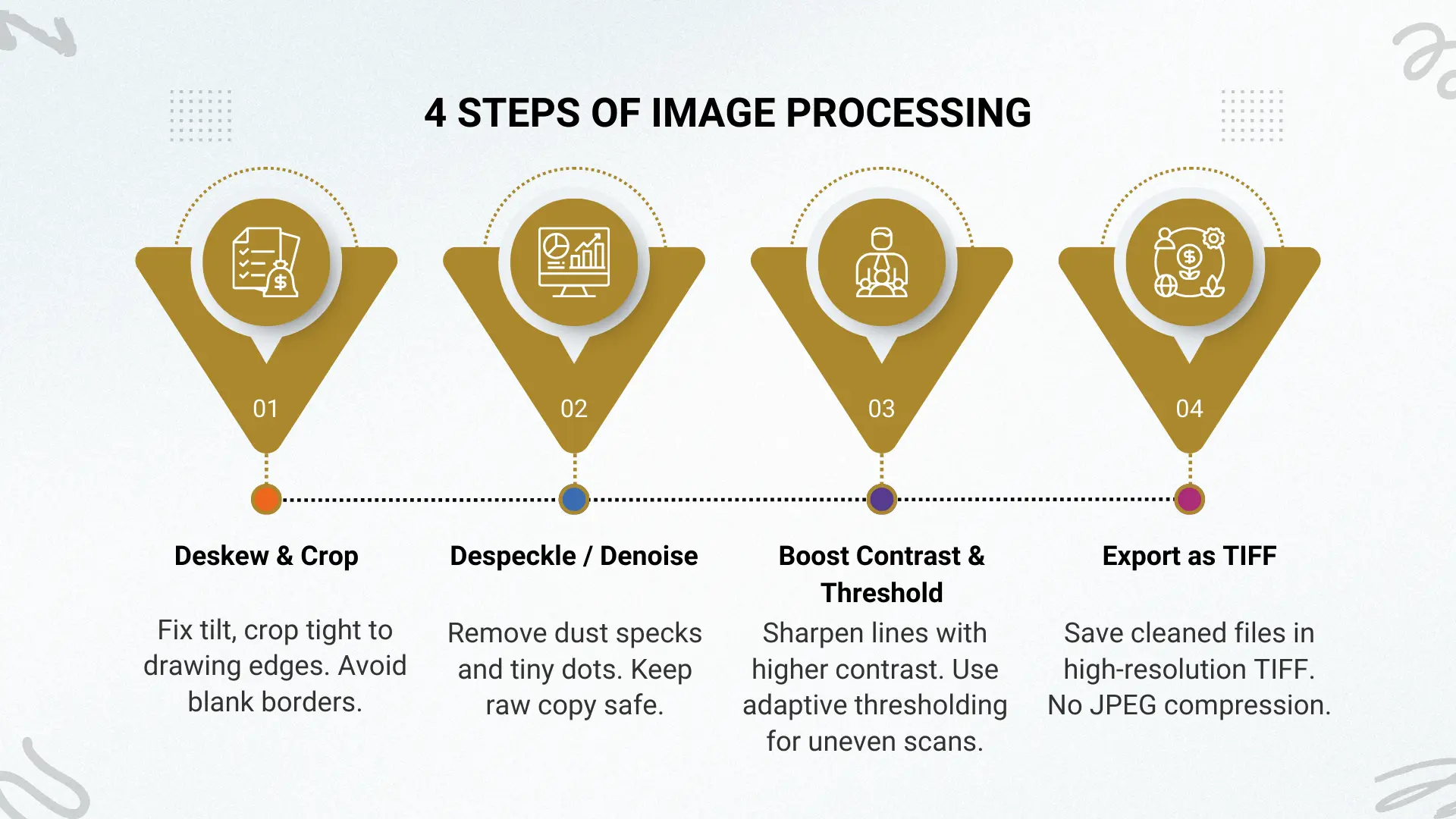
Steps
1. Deskew and crop margins
- If a sheet is even slightly rotated, the traced geometry will be off. Correct tilt first. Crop tight to the drawing extents so blank borders don’t confuse vectorizers or trigger unintended scale detection.
- Quick tip: Many batch scanners and tools (ScanTailor, Acrobat, ImageMagick) offer automatic deskew; verify visually afterwards.
2. Despeckle/remove noise
- Old paper and scanning dust create speckles that vector tools interpret as tiny line segments. Use a light despeckle (median or morphological filters) — not an aggressive blur that eats fine lines.
- For small speckles, remove pixels below a 1–2 px threshold (depending on DPI). Keep a copy of the raw scan in case you over-clean.
3. Adjust contrast and thresholding
- Strong contrast improves line clarity. Increase contrast, then apply thresholding to produce a crisp black-and-white image for linework. Otsu or adaptive thresholding works well when illumination varies across the sheet.
|
Warning |
|
A quick scan won’t always cut it. Run a grayscale pass to catch the softer details, or go with a two-pass approach: one in black and white for the main structure, another in grayscale just for the notes. That way, nothing gets lost. |
4. Convert scanned paper to CAD black-and-white (or reduce colors)
- When it is just clean linework, stick to a black-and-white image. It usually produces the sharpest vectors. If the drawing is covered with colored highlights or markups, scale it back first. Reduce the palette to four to eight colors, then isolate the baselines before pushing the file through vectorization.
- When in doubt, keep a high-quality grayscale master and export the B/W version for vectorization.
5. Save in high-resolution TIFF
- Export the cleaned image as a lossless TIFF. TIFF preserves detail and avoids the compression artifacts that JPEG introduces. Name files clearly (Project_Sheet_01_300dpi.tif) and keep originals in an “archive/raw” folder.
Conversion Methods Explained
There isn’t a single magic button that works for every drawing. Sometimes it is quick and almost boring. Other times it is a fight. Which path you take comes down to three things: the file type, the precision you require, and how much elbow grease you want to spend cleaning up the result. Here are the three most common ways people tackle this.
AutoCAD PDFIMPORT (for vector PDFs)
If you are lucky enough to get a true vector PDF, AutoCAD’s PDFIMPORT is usually the fastest option. The command pulls the linework straight into a DWG: walls, circles, arcs, polylines. It often comes in clean enough that you can start editing right away. For floor plans or detail sheets that were exported from CAD in the first place, it feels almost like magic.
But there are catches. Hatch areas can explode into thousands of little pieces that slow everything down. Text doesn’t always survive the trip; sometimes it turns into outlines instead of editable characters. And if the PDF is really just a raster scan hiding inside a PDF wrapper, the import tool has nothing useful to grab. In short, it’s brilliant when the source file is vector, but unreliable for anything else.
Wondering how to convert scanned paper to CAD (DWG)?
Raster-to-vector tools
Scanned sheets are a different animal. For those, you need raster-to-vector software. Programs like AutoCAD Raster Design, Scan2CAD, or Vector Magic trace the pixels and convert scanned paper to CAD. They are lifesavers when you’ve got a stack of old drawings and no digital originals, especially when there are dozens of sheets to get through.
Quality matters. A crisp, high-contrast scan gives you neat polylines and arcs that need only light editing. A blurry or dirty scan? That can spit out hundreds of tiny, jagged segments that take hours to clean. This is why preprocessing, cropping, despeckling, and boosting contrast pay off. Many firms settle on a hybrid method here: run the conversion to get a base drawing, then tidy it manually in AutoCAD. That mix of speed and human oversight usually produces the best results.
Manual tracing or redraw
Sometimes you can’t take shortcuts. When the stakes are high (think permit sets, fabrication details, structural sheets), you really do not want to gamble on automation. Manual redrawing is still the safest path. A good drafter brings something software cannot: the ability to read intent, notice little inconsistencies, and apply layers the way they should be. The payoff? A drawing that holds together, looks clean, and goes into review without the kind of “how did that slip through?” moments that can derail a project.
The downside, of course, is time. Redrawing a complex sheet line by line is slow. On large projects, it can stretch into days. That’s why many teams mix approaches: start with automation to cover the easy parts, then redraw or trace the critical pieces. It’s not glamorous, but it balances accuracy with efficiency.
The trade-off is time. Redrawing every line manually requires significant effort, especially on complex projects. To strike a balance, many firms use a hybrid approach: run a raster-to-vector conversion to establish the base, then manually trace or adjust critical dimensions, annotations, and geometry. This combination offers both efficiency and confidence in the deliverable.
| Method | Best For | Pros | Cons | Typical Time |
| AutoCAD PDFIMPORT | Vector PDFs from CAD sources | Fast, built into AutoCAD, good geometry retention | Fails on raster content, hatches/text may break | Minutes per sheet |
| Raster-to-Vector Tools | Scanned drawings, raster PDFs, multipage sets | Automates large jobs, speeds initial conversion | Dependent on scan quality, messy output without cleanup | 30–90 minutes per sheet depending on complexity |
| Manual Tracing / Redraw | High-accuracy projects (permits, structural, fabrication) | Maximum control, clean standardized output | Time-intensive, requires a skilled drafter | Hours to days, depending on sheet complexity |
AutoCAD Cleanup Best Practices
Even the best conversion method produces drawings that need polishing. Raw imports often contain extra elements, misaligned geometry, or messy layers. A structured cleanup process ensures your DWG is lean, accurate, and easy to work with.
Essential commands
Every drafter has a handful of commands they run before touching anything else. Three of the most reliable are:
- PURGE: Clears unused blocks, layers, and linetypes. It keeps file size manageable and removes clutter.
- AUDIT: Checks the drawing for errors and repairs them automatically where possible. Think of it as a health scan for the DWG.
- OVERKILL: Deletes duplicate or overlapping geometry, replacing hundreds of redundant lines with a single clean element.
|
Note |
|
Run these in sequence after importing or tracing, and you’ll start with a much cleaner foundation. |
Layer standards
Consistent layering makes the difference between a file that feels professional and one that looks chaotic. Many firms adopt the National CAD Standard (NCS) or the American Institute of Architects (AIA) guidelines. Others follow custom in-house standards, especially for specialty trades.
Here’s an example of how layer mapping might look during cleanup:
Blocks & Xrefs
Repetition is the enemy of efficiency. Replace frequently repeated details (doors, windows, fixtures) with blocks, so edits propagate across every instance.
For larger, multi-sheet projects, external references (xrefs) help manage files. Rather than copying floor plans across multiple sheets, link the plan as an xref so changes update everywhere at once. This not only reduces file size but also keeps drawing sets consistent.
| Old Layer | New Layer | Notes |
| Layer1 | A-WALL | Exterior wall lines |
| 0 | A-DOOR | Converted to door block layer |
| Hatch1 | A-HATCH | Consolidated hatch patterns |
Fonts & text
PDF imports often convert text into fragmented polylines. Replace them with true text styles in AutoCAD. Stick with standard fonts like TXT.SHX or Arial unless a client requires specific types. This step ensures notes, dimensions, and schedules remain editable and searchable.
Deliverables & Handover
The conversion is only valuable if the final package is clear, standardized, and useful to the end client. Deliverables should be predictable and easy to integrate into any workflow.
Standard package
A typical handover should include more than just the DWG. A professional package often contains:
- DWG file (primary deliverable)
- DXF backup for compatibility with non-AutoCAD software
- Vector PDF for easy viewing and plotting
- Raster PDF of the original scan for reference
- Font files/CTB plot styles used in the drawing
- Layer legend or documentation of the mapping applied
- Readme file explaining versions, standards, and any notes
This ensures the client has everything needed to view, edit, and archive the project.
File naming conventions
Naming consistency reduces confusion, especially on projects with dozens of sheets. A reliable pattern is:
ProjectName_SheetNumber_Revision
Example: HospitalRenovation_A102_RevB.dwg
This convention allows quick sorting and makes it obvious which sheet is the latest.
Here’s a simple deliverables checklist you could add to your article:
| Deliverable | Included | Notes |
| DWG file | ✔ | Final editable drawing |
| DXF backup | ✔ | For wider compatibility |
| Vector PDF | ✔ | For plotting/sharing |
| Raster PDF | ✔ | Original scan reference |
| Fonts/CTB | ✔ | Matches delivered DWG |
| Layer legend | ✔ | Explains layer mapping |
| Readme file | ✔ | Version info and notes |
Common Problems & Fixes
Even with the right tools, conversions rarely come out flawless. A few recurring issues tend to slow down projects, but with the right approach, most can be fixed quickly.
- Ghost lines or noise: These usually appear when scanning faint pencil marks or dirty paper. Handle them early with preprocessing tools like despeckle, crop, and thresholding.
- Broken polylines or arcs: Imported drawings often fragment curves into short segments. Use JOIN or PEdit to stitch them back into continuous geometry.
- Text issues: If text imports as outlines, retype it using a standard font or apply a font mapping table to replace exploded characters.
- Scale mismatches: Confirm three known dimensions in different parts of the drawing. If mismatches appear, rescale the file with the ALIGN or SCALE
|
Top 3 Issues That Cause Project Delays
|
Cost & Time Expectations
Typical timelines
Turnaround time varies dramatically based on file type and project complexity. A clean vector PDF might convert scanned paper to CAD in a few hours. A large, detailed mechanical-electrical-plumbing (MEP) set could require several days or even weeks, especially if redrawing is needed.
Pricing models
Vendors structure pricing differently:
- Per sheet: common for large sets with predictable layouts.
- Per hour: flexible for smaller or irregular projects.
- Project-based: useful when the scope is complex and deliverables extend beyond simple conversions.
According to industry averages, the cost per A1 sheet conversion ranges from $25–$75, depending on complexity and quality requirements. Simpler architectural plans fall toward the lower end, while intricate MEP layouts demand more time and skill, raising costs.
Choosing the Right Conversion Vendor
Outsourcing can save significant time, but the vendor must be vetted carefully. A weak partner can deliver messy files that require rework, costing more than they save.
RFP checklist
When preparing a Request for Proposal (RFP), make sure you ask about:
- Sample deliverables: Request a pilot sheet to judge quality.
- QA process: Confirm that vendors run dimension checks and standardized cleanup steps.
- Security/NDAs: Ensure sensitive project files are protected.
Here’s a sample vendor scoring matrix you could adapt for internal evaluation:
| Criteria | Weight | Vendor A | Vendor B | Score |
| Accuracy of sample files | 40% | High | Medium | A: 90, B: 70 |
| Turnaround time | 25% | 2 days | 5 days | A: 85, B: 65 |
| Cost competitiveness | 20% | $$ | $ | A: 80, B: 90 |
| Security protocols | 15% | NDA, ISO cert. | NDA only | A: 95, B: 70 |
FAQs
These short, direct answers are designed for snippet capture and AI visibility.
What DPI should I scan blueprints at?
For CAD conversion, 300 DPI is standard. Use 400–600 DPI if drawings contain fine details or faint linework.
Should I use PDF or TIFF for CAD conversion?
TIFF is best for high-quality conversions since it’s lossless. PDF is convenient for sharing, but it may be compressed.
Can AutoCAD convert scanned paper to CAD automatically?
Only vector PDFs can be imported directly. Scanned raster drawings require raster-to-vector tools or manual tracing.
How long does scan to CAD take?
A simple floor plan might take a few hours. Complex multi-sheet MEP scans can require several days or longer.
What deliverables should I expect?
Typical packages include DWG, DXF backup, vector PDF, raster PDF, font/plot files, and a readme or layer legend.
How do I fix broken lines after conversion?
Use AutoCAD commands like JOIN or PEdit to combine fragmented polylines into clean geometry.
Why does text sometimes appear as outlines?
PDF imports often vectorize text. Replace these outlines with true editable fonts during cleanup.
What’s the average cost per sheet?
Industry rates range from $25–$75 per A1 sheet, depending on detail, quality, and turnaround requirements.
Can I use JPG scans for CAD conversion?
You can, but it’s not recommended. JPG introduces compression artifacts. TIFF or high-resolution PDF is better.
Do vendors keep my project data private?
Reputable vendors sign NDAs and use secure transfer methods. Always ask about their security protocols before sending files.
Conclusion
Turning a pile of scans into crisp CAD drawings is not just possible; it can be surprisingly smooth when the right steps are followed. You already know the basics: scan carefully, preprocess wisely, convert smartly, and clean up with care. The tricky part is finding the hours to actually make it happen while juggling real projects and looming deadlines.
That is exactly where Cad Drafter shines. We take the hassle off your desk and give you back polished DWG files that are ready to roll. Think of us as your drafting pit crew, working behind the scenes while you drive the project forward.
Ready to see the difference? Upload your drawings today and grab a free quote to convert scanned paper to CAD. It is quick, it is simple, and it might just be the easiest win you score all week.