Common Challenges in P&ID Creation and How AutoCAD Plant 3D Toolset Solves Them
In the construction process, drafting P&IDs (Piping and Instrumentation Diagrams) is a difficult task, more like a process of navigating the issues of lines and symbols. One cannot understand the intricacies of Piping and Instrumentation Diagrams without essential knowledge, understanding, and expertise. Eventually, it leads to inconsistencies in the design process.
When we talk about any kind of construction project, it is difficult to negate the necessity of P&ID. You must think about this and its role in the design process. Here is a brief introduction to it. Piping and Instrumentation Diagram is explained as an attention-to-detail graphical representation and technical drawing that is extensively used in Mechanical Engineering. These diagrams show the linkage between pipes, equipment, and instruments that are used in the industrial process. It tells you about the layout and connection among the components to perform the functions.
To dive deeper into construction design and CAD solutions, explore our comprehensive article on 3D modeling features and plugins for architects.
Worried About Seamless P&ID Creation?
Here is the catch. Given the complex nature of diagrams, it is impossible to negate the existence of challenges lying ahead in the project execution. These challenges revolve around manual irregularities, sub-standard processes, and a time-consuming drafting process. The good news is that you can avoid and eliminate these potential roadblocks. Here is the solution in the form of the AutoCAD Plant 3D Toolset. By leveraging this toolset, you can easily pursue the P&ID and enhance the efficiency of your project. Hold up your horses. This blog will explore the challenges one can face in creating a P&ID and how you can address them using the AutoCAD toolset.
What is Meant By Piping and Instrumentation Diagram?
Before going into the details of the challenges associated with P&ID, you must understand the meaning and purpose of P&ID. A Piping and Instrumentation Diagram refers to the graphical drawings that are used for portraying the layout process and links among the different components during the design phase.
Key Features of P&ID
Piping
It includes pipe sizes, types, and directions. The Pipes are shown as lines, exhibiting the network of pipes that are used for transporting the fluids throughout the process.
Instruments
The instrumentation part includes devices that are used to control, measure, and monitor the variables used in the process. The common instruments include sensors and transmitters that are used to measure the flow, pressure and transmit the signals. Controllers receive the signals from transmitters and send the signals to control devices. Moreover, indicators and gauges also display parameters to operators.
Control Loops
It shows how the system is controlled throughout the process.
Importance of P&ID in Designing & Engineering
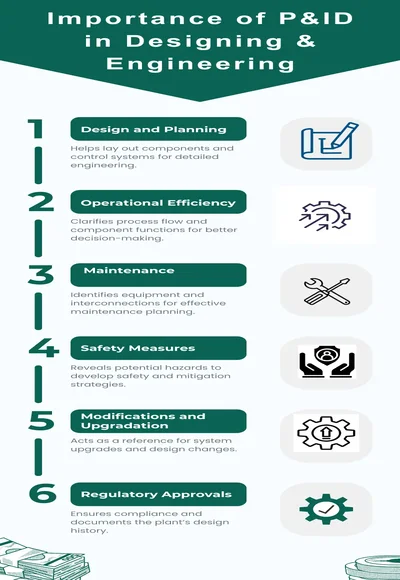
Design and Planning
During the initial design phase, P&IDs are necessary for laying out the plant’s components, determining pipe sizes, specifying instrumentation, and control systems. These drawings serve as the basis for more detailed engineering drawings.
Operational Efficiency
In the case of operations, P&IDs provide a clear understanding of the process flow, the function of each component, and how the control systems work. So you can make informed decisions.
Maintenance
For maintenance, the team also depends on Piping and instrumentation diagrams to identify equipment, comprehend system interconnections, and plan robust maintenance activities.
Safety Measures
P&IDs are also essential for various safety studies and analyses. By visually representing the process, potential hazards can be identified and averted by developing different mitigation strategies.
Modifications and Upgradation
P&IDs also serve as the baseline documentation in the case of tangible changes and expansions, helping engineers to understand the existing system and design for effective upgrades.
Regulatory Approvals
P&IDs are often required for ensuring regulatory compliance and serve as a historical record of the plant’s design.
For detailed insights into tools that enhance construction drawing accuracy, see our guide on best BIM software comparison worldwide.
Common Challenges in P&ID Creation
As it is mentioned earlier that drafting the piping and instrumentation diagrams for the project is not bereft of roadblocks. One can face these challenges during Plant Design Engineering. Here are the details of the challenges.
Challenge 1: Inconsistencies in Process Data
One of the biggest challenges the engineers face during the Piping and Instrumentation Diagrams drafting is the presence of inconsistencies and irregularities in data. These diagrams serve as the blueprints for the plants. Given its importance, any inaccuracy in the data can have a dangerous impact on the viability of P&ID. There can be multiple sources of irregularities. The manual handling of data can also obstruct the process of drafting. In the same manner, inconsistent use of symbols & tags, and mislabeling of equipment further complicate the data. Moreover, the absence of standard data formats can also give rise to errors and hamper the progress of the design process.
Solution
So, before initiating the drafting process, engineers must invest some time in gathering detailed and error-free process information to avoid any kind of discrepancy throughout the procedure. In this regard, AutoCAD 3D Toolset can be handy to address these issues. It comes with libraries of industry-proven symbols for piping, instrumentation, and equipment. Moreover, it allows you to understand the rules to check the accuracy of P&IDs.. Through tagging and annotation, you can also standardize the tags, thereby eliminating the risk of errors. These annotations are often linked to data so they can reflect the correct information.
Challenge 2: Complex and Time-Consuming Drafting
Another challenge that hampers the creation of P&IDs is the complexity of design and time-consuming drafting based on the components. We acknowledge that these diagrams represent complex systems with precise detail for equipment, piping, and instrumentation. For better accuracy, these diagrams must precisely show the connections between different components, such as pipes, valves, sensors, and control devices based on the diagrams. Managing these complex details without any significant and advanced tools can lead to errors, making it impossible to ensure the correct representation of all the related components.
Solution
AutoCAD Plant 3D offers specialized tools designed to manage complex diagrams easily. Its intuitive and seamless interface allows users to create and modify P&IDs with precision. The software delivers a comprehensive library of industry-standard symbols and components, ensuring that all elements are accurately represented without any confusion. Additionally, through specification-driven design, you can explain the pipe specifications by adhering to the industry standards. The software also facilitates automatic connection of pipes and intelligent routing based on the well-defined paths. This property can reduce the manual efforts in drafting and make the creation easy and without any difficulty.
Challenge 3: Data Management as a Daunting Task
When it comes to Industrial projects, it is hard to ignore interconnected components. While understanding its specifications, data management becomes a difficult task due to outdated software. In this regard, clearly showing their relationships without cluttering and damaging the essence of the diagram is a common challenge that experts face while dealing with large-scale projects. Moreover, inability to keep up with the technologies and frequent changes can further exacerbate the challenge.
Solutions
In the AutoCAD Plant 3D Toolset, data can be properly managed by storing it in a SQL database. Any updates to one part of the P&ID ( tag number, specification) are reflected across all relevant components and documentation. By managing the data effectively and layering and labeling it correctly, one can avoid this challenge smartly.
Challenge 4: Balancing Standardization with Customization
During the design process, one must ensure that P&IDs comply with industry standards and regulations for better safety measures and efficiency. Any kind of non-compliance can cause financial losses and costly rework, indefinite project delays, and even increase safety issues. Different industries and regions have specific standards for P&IDs, such as ISA and ISO. Therefore, based on unique project requirements, it becomes difficult to balance the customized options with standard protocols, limiting flexibility or missing client-specific requirements.
Solution
AutoCAD Plant 3D also the process of balancing the standardization with personalization by supporting a wide range of proven industry standards, and allows users to create P&IDs that live up to the expectations of regulatory approvals. The software offers CAD Customization templates and the latest symbol libraries that adhere to various compliant standards and codes, ensuring the diagrams fulfill the required specifications. AutoCAD also allows users to customize these templates tailored to organizational standards. Furthermore, AutoCAD Plant 3D allows the enforcement of P&ID templates to reduce the chances of mishap.
Challenge 5: Tangible Disconnection between P&ID and Plant 3D Model
Another common challenge in P&ID drafting is the tangible disconnect between the 2D P&ID drawings and the 3D plant model. 2D drawings show 3D objects on a flat plane. This natural limitation makes it highly challenging to understand the plan layout. Engineers can make mistakes when they translate 2D drawings into a 3D reality, leading to errors that are often not discovered until late in the design process.
Solution
This toolset has the potential to address this issue by offering an integrated workflow between the P&ID and 3D plant model. Instead of drawing 2D symbols, the 3D toolset allows users to utilize intelligent 3D models of equipment and piping. When a P&ID is developed in the Plant 3D tool, the components are automatically generated in the 3D form based on P&ID data. This smooth integration not only generates the components but also allows for the automatic generation of reports and documents such as equipment lists, piping specifications, and valve schedules. This eliminates the disconnection and delivers accurate pictures based on data.
Challenge 6: Keeping Up with Frequent Changes in the Design Process
During the design phase, frequent changes occur throughout the process. These changes range from style modification, design upgrades, pipe size, pipe design, and changes in the layout of the process. Inability to keep up with the frequent changes can cause severe challenges.
Solution
Here is the solution. During the design process, the effective use of digital tools such as AutoCAD Plant 3D and SmartPlant can reduce the chance of excessive modifications. The advanced software enables the engineers to monitor document revisions and manage these upgrades at an early stage.
Challenge 7: Limited Reporting and Documentation
Comprehensive documentation and reporting are essential for project management and operational efficiency. Generating detailed reports and maintaining comprehensive documentation manually can be tiring. By reporting the process manually, not only damage the credibility but also derails the process.
Solution
By using AutoCAD Plant 3D, the users can streamline documentation and reporting and reduce the chances of limited reports. The software can generate a wide range of reports, including equipment lists, line lists, and instrument indexes, accurately based on the data of P&ID. These reports can be personalized according to project requirements. Moreover, AutoCAD Plant 3D’s integration with other Autodesk tools helps in the creation of comprehensive project documentation. So you can manage your process effectively.
Challenge 8: Poor Integration Between Instrumentation and Control Systems
Instrumentation and control systems are important components of any process plant. Incorrect representation and poor integration of these essential elements can lead to operational inefficiencies or damage the safety protocols.
Solution
To avoid such poor integration, engineers must refer to instrumentation datasheets and system diagrams during the creation of piping and instrumentation Diagrams. They must use AutoDesk Docs for better collaboration and representation to get proper access control on the components.
Tips to Better Leverage the AutoCAD Plant 3D Toolset for Maximum Outcomes!
| Serial no | Best-Suited Tips | How to Leverage Your Maximum Outcomes |
| 1 | Customize the Software | Always use the customized AutoCAD Plant 3D to meet specific company standards and project requirements.
|
| 2 | Use SQL Server Instead of SQLite | For industrial projects, always use SQL Server for database management instead of SQLite for better security and performance. |
| 3 | Create and Customize Specs and Catalogs | So your project will reflect your requirements and produce lucrative results.
|
| 4 | Comprehend Automated Pipe Routing | You must understand this tool to improve the efficiency and precision of your piping designs. |
| 5 | Utilize Equipment Templates: | You can save time and ensure consistency by using equipment templates for piping components. |
Are You Looking for Professional Guidance Regarding the AutoCAD Plant 3D Toolset?
If you have undertaken your industrial project and are clueless about design processt how to deal with challenges in the creation of P&IDs, turn to CAD Drafter. We excel at delivering consultation and CAD drafting services for all kinds of structural projects by using advanced software such as AutoCAD Plant 3D Toolset and AutoCAD. This is why the CAD Drafter is here at your service to guide you throughout the challenges and solve them by using the software. Our experts possess in-depth knowledge regarding CAD services and technologies and understand the project requirements. Our deliverables include plant layout design, piping thickness calculation, pipe stress analysis, structural analysis, and optimized pipe routing. Our 3D modeling services bring efficiency and transparency to your project. After analyzing the project, our expert drafters offer the best storage solutions tailored to your project needs and turn your piping blueprints into attention to detail and precise drafts. With our in-depth industry knowledge, we unlock the success of your project. Whether you’re designing a new plant or modifying an existing facility, our team ensures clear documentation, collaboration, and local & regional regulatory approval. Contact us now for expert services!
Final Thoughts
To conclude that, creating precise P&IDs is an essential aspect of process plant design and operation. But the challenges involved in this task can derail the process and cause losses for your project. Worry no,t! AutoCAD Plant 3D offers top-notch solutions by addressing all the issues. Hire our professional CAD services for outstanding and accurate P&ID drafting services. To further explore the services that we offer, visit our website now!
Frequently Asked Questions
-
What is the difference between AutoCAD P&ID and Plant 3D?
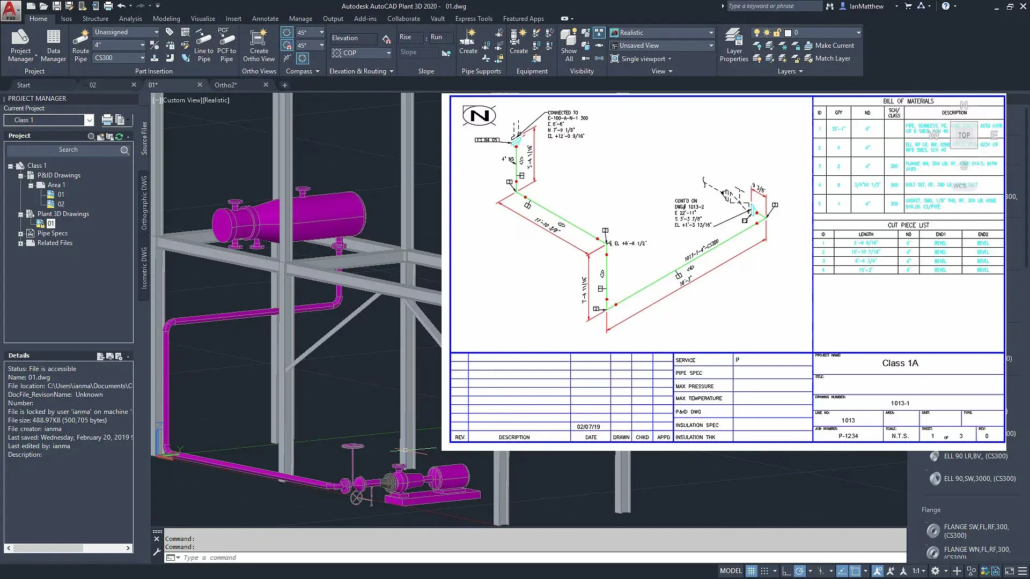
AutoCAD P&ID focuses on developing 2D piping and instrumentation diagrams. On the contrary, AutoCAD Plant 3D Toolset is a complete set that offers not only AutoCAD P&ID functionality but also adds 3D modeling capabilities.
-
How to make p&id using AutoCAD?
By using several steps, you can create a P&ID
- Open the software
- Create a New P&ID Drawing
- Insert the symbols
- Connect the lines
- Add tags and annotations
- Validate the drawings
- Save the database
-
What are the benefits of AutoCAD Plant 3D?
The benefits include
- Accurate Designing plants
- Operational efficiency
- Data management
- Accurate reporting
- Accurate symbol libraries
- Isometric & Orthographic Drawings
-
How do I convert Plant 3D P&ID to AutoCAD?
- Open the P&ID in AutoCAD Plant 3D.
- Use the option of Export
- Use ETRANSMIT to share the drawing

