Siemens NX Made Easy: A Comprehensive Roadmap from CAD Design to 5-Axis CAM
In the long history of Computer-Aided Design, Unigraphics sits in a rare category. It isn’t just remembered. It’s respected. What began as an early 3D modeling system has grown into what most engineers now recognize as Siemens NX. It is a platform built less for convenience and more for capability.
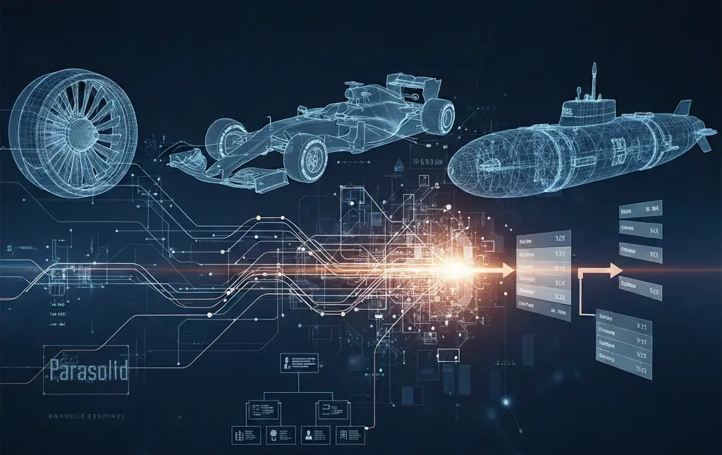
This is not software meant for quick, throwaway models. NX lives where tolerances are unforgiving, and failure is expensive. Jet engine turbine blades. Formula 1 bodywork tuned to airflow by millimeters. Submarine assemblies with thousands of interdependent parts. These are not edge cases for NX. They are the point.
For engineers transitioning into a Unigraphics-driven environment, the initial experience can feel dense, even overwhelming. Menus stack. Workflows branch. Tools behave differently than expected. It’s common to feel productive one moment, completely lost the next.
This guide exists for that exact gap. It strips away the noise and focuses on how NX actually thinks through the entire manufacturing integration process. Not shortcuts. Not gimmicks. Just a clearer path through one of the most capable CAD systems ever built.
Understanding the NX Ecosystem: Beyond Simple CAD
To work effectively with Siemens NX, one must first understand that it is not merely a “drawing tool.” It is a foundational pillar of Product Lifecycle Management (PLM). Unlike mid-range CAD software, NX is built on the Parasolid kernel (the most accurate geometric modeling engine in existence) developed by Siemens itself.
The Power of Integration
The true “Unigraphics advantage” lies in its seamless integration. In traditional workflows, an engineer designs a part in one software, exports it to another for stress analysis (CAE), and then to a third for machining (CAM). Every “hand-off” risks data corruption or loss of associativity.
In NX, these environments coexist. When you change the diameter of a bolt hole in the CAD environment, the stress analysis meshes and the CNC toolpaths update automatically. This is known as Master Model Technology, and it is the secret to the speed of modern aerospace and automotive giants.
Core Pillars of the NX Interface and User Experience
Just like open source CAD software, the first hurdle to making NX “easy” is mastering its interface. Siemens has invested heavily in the Adaptive UI. It uses machine learning to predict which command you will need next based on your previous actions.
Roles and Customization
One of the most powerful but underutilized features is the “Role.” An industrial designer needs different tools than a mold-and-die specialist.
- The Essentials Role: Strips away advanced clutter for beginners.
- The Advanced Role: Provides full access to surfacing and analysis.
- Custom Roles: Companies can lock down specific toolbars to ensure all engineers follow the same internal standards.
The Selection Intent Logic
Beginners often struggle with selecting edges or faces. NX utilizes Selection Intent, which allows you to define rules like “Feature Faces” or “Tangent Curves.” By selecting a rule rather than an individual edge, your model becomes “robust.” If the underlying geometry changes, the selection rule adapts, preventing the dreaded “broken link” symbols in your part navigator.
Synchronous Technology: The Game Changer
If there is one feature that makes working with Unigraphics/NX “easy,” it is Synchronous Technology (ST). Historically, CAD was divided into two camps: History-Based (parametric drafting) and Direct Modeling.
- History-Based: You must understand how the part was built to change it. If you delete a sketch from the beginning, the whole model breaks.
- Direct Modeling: You can push and pull faces, but you lose the mathematical intelligence of parameters.
Siemens NX Synchronous Technology combines both. It allows you to treat “dumb” geometry (like an imported STEP or IGES file from a client) as if it were a native, intelligent model.
Why Synchronous Technology is Essential
- Editing Third-Party Data: You can move a hole on a part sent by a supplier even if you don’t have their original design history.
- Rapid Iteration: In a brainstorm session, you can “drag” a wall to thicken it without opening sketches and recalculating constraints.
- Geometric Intelligence: ST recognizes “intent.” If you move one boss in a circular pattern, NX is smart enough to ask if you want to move the entire pattern, even if the pattern wasn’t explicitly defined.
| Feature | Traditional Parametric | Synchronous Technology |
| Modification Speed | Slow (requires sketch editing) | Fast (direct interaction) |
| Flexibility | Rigid (order dependent) | Fluid (order independent) |
| Imported Data | Difficult to edit | Easy to edit |
| Learning Curve | High | Intuitive |
High-Performance Sketching and Part Logic
Every great design begins with a sketch, but in NX, sketching has undergone a revolution. The New Sketcher (introduced in recent versions) does away with the need to manually define every single constraint (Horizontal, Vertical, Tangent).
The “Inferred” Constraint Revolution
Instead of spending 10 minutes ensuring a line is perfectly perpendicular, the NX sketcher “infers” the relationship. It recognizes geometric patterns in real-time. This reduces the number of clicks by up to 30%, making the initial phase of design significantly faster.
Reference Geometry and Datums
A common mistake in Unigraphics is “sketching on air.” To make NX easy and stable, professional users rely on Datum Planes and Coordinate Systems (CSYS).
- The Best Practice: Always link your first sketch to a Fixed Coordinate System at $[0,0,0]$.
- Why it Matters: When you later assemble 500 parts, having a consistent “Home” position prevents parts from flying off into 3D space.
Learn How To Deal With Siemens NX and 5-Axis CAM
Strategic Value of NX in Industry
To understand why companies pay a premium for NX over cheaper alternatives, we must look at the Product Complexity Matrix.
| Industry | Critical NX Feature | Impact |
| Aerospace | Composite Design & Advanced Surfacing | Reduces weight while maintaining structural integrity. |
| Automotive | Large Assembly Management | Allows 50 engineers to work on the same car chassis simultaneously. |
| Medical Devices | Convergent Modeling | Seamlessly integrates 3D mesh scans of human bones with CAD geometry. |
| Consumer Electronics | Industrial Design (Realize Shape) | Enables “Subdivision Modeling” for ergonomic, fluid shapes. |
Mastering Large Assembly Management: The “Top-Down” Revolution
In many CAD programs, as soon as you surpass 500 components, the software begins to stutter. Siemens NX is built differently. It is designed to handle assemblies with over 1,000,000 components, think of a Boeing 777 or a nuclear aircraft carrier. The secret to working with such scale without frustration lies in the Assembly Navigator and Loading Options.
Lightweight vs. Exact Representations
One of the most powerful features for performance optimization is the use of JT (Jupiter Tessellation) data or “Lightweight” representations.
- Exact: Loads the full mathematical Parasolid data. Essential for detailing and machining.
- Lightweight: Loads a graphical facet representation. This allows you to rotate a massive engine assembly with buttery-smooth frame rates because the CPU isn’t calculating every underlying curve.
The Power of Top-Down Design and WAVE Linking
Traditional CAD often uses “Bottom-Up” design (build parts, then put them together). Professional NX users utilize Top-Down Design. This starts with a “Skeleton” or “Control Structure” at the top level of the assembly.
Using WAVE Geometry Linker, you can “project” geometry from the skeleton down into individual parts.
Advanced Surfacing: The Art of Class-A Geometry
While solid modeling is for “mechanical” parts, Surface Modeling is where NX truly shines in the automotive and aerospace sectors. To make surfacing easy, you must move beyond simple extrudes and revolves into the world of Freeform modeling.
Realize Shape: Subdivision Modeling (Sub-D)
For years, creating organic, ergonomic shapes (like a computer mouse or a car’s side mirror) was a painstaking process of managing individual splines and poles. NX introduced Realize Shape, a toolset based on subdivision modeling.
Imagine starting with a sphere of “digital clay.” By pushing and pulling on a cage-like structure, you can create complex, fluid shapes that maintain G2 or even G3 (Curvature) continuity automatically. This tool has bridged the gap between industrial designers (who want beauty) and engineers (who want manufacturability).
Global Shaping and Deformable Parts
NX allows for “Global Shaping,” where you can take a flat, finished design—like a tread pattern for a tire—and “wrap” it around a complex 3D surface.
Furthermore, Deformable Parts allow you to create components like springs or rubber seals that “deform” based on the assembly constraints. In other CAD tools, a spring is a static object; in NX, as you move the piston, the spring physically compresses in the 3D model.
Convergent Modeling: Merging Scanned Data with CAD
Historically, working with 3D scan data (STL files or polygon meshes) was a nightmare. You couldn’t add a hole to a scan or trim it with a CAD plane because they were different mathematical languages.
Convergent Modeling in NX allows you to perform Boolean operations (Unite, Subtract, Intersect) on mesh data and Parasolid data simultaneously.
The Workflow of the Future
- Scan: You scan a vintage car engine block.
- Import: You bring the STL mesh directly into NX.
- Modify: You use standard CAD commands to “cut” a new mounting bracket directly into the mesh.
- Print: You send the hybrid part directly to a 3D printer or a CNC machine.
| Feature | Traditional Reverse Engineering | Convergent Modeling in NX |
| Data Type | Manual “re-drawing” over the scan | Direct editing of the scan |
| Time to Market | Weeks of surfacing | Hours of direct modeling |
| Accuracy | Prone to human error | Maintains 1:1 scan fidelity |
Integrated Validation and Simulation (CAE)
Working with NX becomes “easy” when you stop guessing if your part will break. Simcenter 3D, built directly into the NX interface, allows for “Design-Integrated Simulation.”
Stress, Strain, and Thermal Analysis
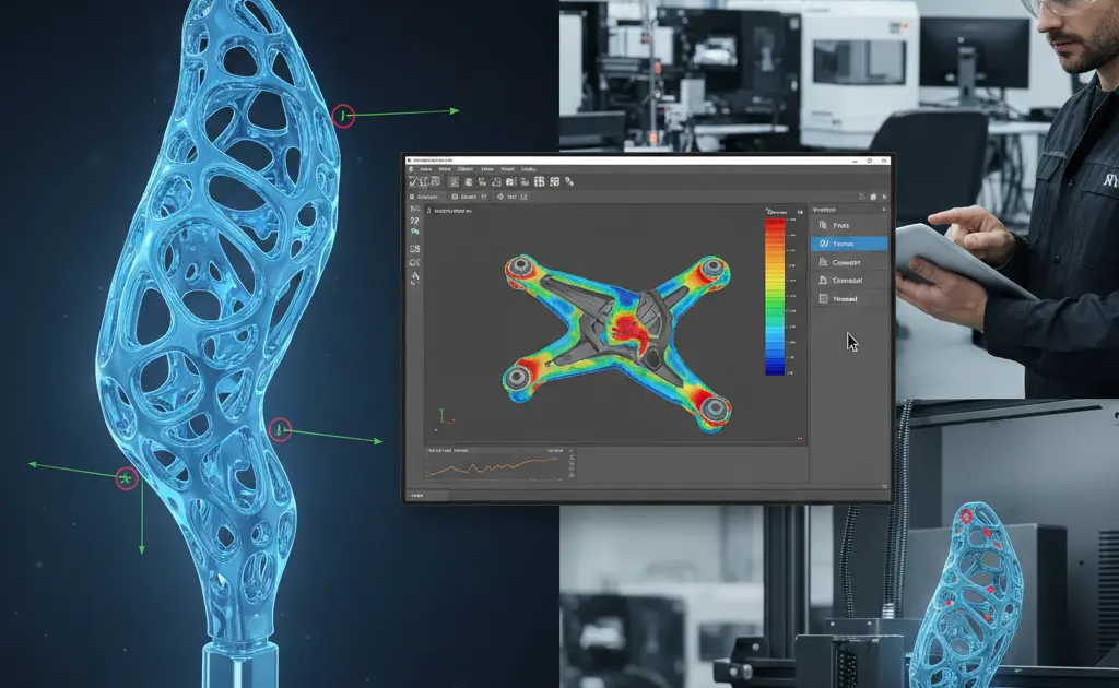
You don’t need to be a Ph.D. in Finite Element Analysis (FEA) to perform basic checks. NX provides a wizard-driven environment where you can apply a “Force” to a face and see a heat map of the stress.
- Optimization: The “Topology Optimization” feature can actually design the part for you. You tell NX where the loads are and where the part needs to be bolted, and the software “grows” the most efficient, lightweight shape possible—often resulting in organic-looking parts that are perfect for additive manufacturing.
Technical Data and Hardware Optimization
To ensure Unigraphics runs smoothly, your hardware configuration is just as important as your software skills. NX is heavily dependent on Single-Core Clock Speed for modeling and Multi-Core Parallelism for rendering and simulation.
Hardware Recommendations for NX
| Component | Minimum Specification | Professional Recommendation |
| CPU | Intel i7 / AMD Ryzen 7 | Intel i9 / AMD Threadripper (High GHZ) |
| GPU | NVIDIA RTX 4000 (SFF) | NVIDIA RTX A6000 or equivalent (Certified Drivers) |
| RAM | 32GB | 128GB (Essential for Large Assemblies) |
| Storage | NVMe M.2 SSD | NVMe Gen4/5 Raid 0 for fast scratch disk |
The Importance of Certified Drivers: Unlike gaming, NX requires “Enterprise” or “Studio” drivers. Using a standard gaming driver can lead to “ghosting” where lines remain on the screen after you’ve deleted them, or frequent crashes during complex boolean operations.
The “Master Model” Strategy in Production
The pinnacle of NX efficiency is the Master Model Principle. This is a file management strategy where the “Design Part” is never directly touched by the CAM or CAE specialist. Instead, they “Reference” the master file into their own environment.
Why this is a “Better” way to work:
- Concurrent Engineering: The CNC programmer can begin writing toolpaths while the designer is still finishing the fillets.
- Automated Updates: When the designer changes a radius on the master part, the CAM programmer simply hits “Regenerate,” and the toolpath adjusts without having to re-select any edges.
- Version Control: It prevents the nightmare of having “Part_v1_Final_REAL_FINAL.prt” files. There is only one Master Model.
The NX CAM Revolution
The ultimate goal of any engineering project is to bring a product into the physical world. While many CAD platforms rely on third-party plugins for manufacturing, Siemens NX CAM is a native powerhouse. It is widely considered the gold standard for high-complexity machining, particularly in the aerospace and medical industries where 5-axis simultaneous milling is the norm.
The Power of Integrated CAM
Working with NX CAM is “made easy” by its total associativity with the CAD model. If a design engineer changes the depth of a pocket in the 3D model, the CAM programmer does not need to start over. The toolpath is “aware” of the geometry. A simple click on the Regenerate button recalculates the tool motions, ensuring that the machine on the shop floor is always cutting the most current version of the part.
Advanced Toolpath Strategies
NX CAM offers specialized modules that automate the most difficult machining tasks:
- VoluMill and High-Speed Machining (HSM): These algorithms maintain a constant tool load, allowing for significantly deeper cuts and faster spindle speeds. This can reduce cycle times by up to 70% and extend tool life by 300%.
- 5-Axis Lead/Lag and Tilt: Avoidance: In 5-axis machining, the greatest risk is a collision between the tool holder and the workpiece. NX uses “Auto-Tilt” logic to sense upcoming collisions and automatically pivot the tool axis to clear the obstacle.
- Robotic Machining: NX isn’t limited to CNC mills. It supports the programming of 6-axis industrial robots for tasks like fiber placement, trimming, and large-scale additive manufacturing.
The Digital Twin of the Machine Tool: Simulation and G-Code
Being a contractor, you would have an idea of digital twins and IoT. In traditional CAM, there is a “leap of faith” between the software and the machine. Engineers often use a separate software to verify G-code. Siemens NX eliminates this through Integrated Simulation and Verification (ISV).
G-Code Driven Simulation
Unlike basic “Internal” simulation that only shows the tool movement, NX ISV simulates the actual G-code that will run on the controller (Fanuc, Siemens Sinumerik, Heidenhain). This means you see the machine’s actual limits, axis speeds, and potential over-travels on your screen before you ever load a tool.
Post-Processing: The Universal Translator
A CAM system is only as good as its Post-Processor—the code that translates the 3D toolpath into the specific language of your CNC machine. NX includes the Post Configurator, a modern interface that allows users to “tweak” their machine code without needing to be a computer programmer. Whether you are running a 1990s Haas or a brand-new DMG Mori, the Post Configurator ensures the output is “clean” and requires zero manual editing by the operator.
High-Level Features for Industry 4.0
As we move into the era of smart manufacturing, NX is leading the charge with features that integrate the factory floor with the design office.
PMI (Product and Manufacturing Information)
One of the most significant shifts in modern engineering is the move toward Model-Based Definition (MBD). In this workflow, you do not create 2D paper drawings. Instead, you attach dimensions, tolerances (GD&T), and surface finish requirements directly to the 3D model as PMI.
- The Benefit: NX CAM can “read” this PMI data. If a hole is labeled with a specific tolerance in the PMI, the CAM software can automatically select the correct drill and reamer to achieve that tolerance, virtually eliminating human programming error.
Additive Manufacturing Integration
NX is a leader in Design for Additive Manufacturing (DfAM). It includes tools for lattice structures (lightweighting parts while maintaining strength) and support structure generation for metal 3D printing. Because it is an end-to-end system, you can design the part, simulate the 3D printing process to check for thermal warping, and then program the CNC finish-machining—all in one file.
Technical Performance Checklist for Power Users
To keep Unigraphics/NX running at peak efficiency, professional users follow a strict “Data Hygiene” checklist.
| Action Item | Technical Reason | Frequency |
| Part Cleanup | Removes “ghost” objects and fixes underlying geometry math. | Weekly / Before Release |
| Examine Geometry | Identifies “tiny objects” or “self-intersections” that cause CAM errors. | Before Simulation |
| Update External Links | Ensures WAVE links are synced across the assembly. | Daily |
| Clear Temp Files | Frees up the “scratch disk” space for Parasolid calculations. | Monthly |
Building a Career as a Siemens NX Specialist
Unlike cloud-based CAD collaboration, Siemens NX does not rely on remote internet access. Because it is a high-end tool, the professionals who master it command some of the highest salaries in the engineering world. Whether you are a Designer, a Stress Analyst, or a CAM Programmer, specialization is the key to career longevity.
Path 1: The Design Architect
Focus on Advanced Surfacing and Product Definition. These roles are critical in automotive styling and consumer electronics. Mastery of “Realize Shape” and “Class-A Surfacing” is essential here.
Path 2: The Manufacturing Engineer
Focus on Multi-Axis Milling and Post-Processor Development. Companies using multi-million dollar machines need experts who can guarantee that the code will not crash the machine.
Path 3: The PLM/BIM Administrator
Focus on Teamcenter Integration. Teamcenter is the data management backbone for NX. Experts who can manage the flow of data between thousands of users are the “IT Architects” of the engineering world.
The Strategic Conclusion: Why NX Wins
Working with Unigraphics/NX is made “easy” not by simplifying the engineering, but by providing tools powerful enough to handle the complexity. It is a software that grows with you. A beginner can use it to draw a simple bracket, but a master can use it to simulate the airflow over a supersonic wing.
The transition to NX is an investment in certainty. By using the Master Model principle, Synchronous Technology, and Integrated Validation, you eliminate the “guesswork” that plagues smaller-scale operations. You aren’t just drawing; you are creating a digital twin that carries all the intelligence needed to build, test, and maintain a product for its entire lifecycle.
In a world where speed-to-market is the ultimate competitive advantage, Siemens NX provides the shortest path from a “napkin sketch” to a finished, high-performance product.
Frequently Asked Questions (FAQ)
Is Siemens NX the same as Unigraphics?
Yes. Unigraphics (UG) was the original name of the software. After Siemens acquired it, they rebranded it as NX. While the name changed, the core “Parasolid” engine and many of the legacy commands remain, though they have been modernized with a significantly more intuitive user interface.
What makes NX better than mid-range CAD like SolidWorks or Inventor?
The primary difference is scalability. While mid-range tools are excellent for small-to-medium assemblies, NX is engineered to handle hundreds of thousands of parts without system failure. Additionally, NX’s “Synchronous Technology” and integrated high-end CAM/CAE offer a level of depth that general-purpose tools cannot match.
Can I run Siemens NX on a standard gaming laptop?
Technically, yes, but it is not recommended. NX requires ECC RAM and Workstation-class GPUs (like NVIDIA RTX A-series) for stability. Gaming cards (GeForce) are optimized for frame rates, whereas Workstation cards are optimized for geometric accuracy and certified to prevent crashes during long modeling sessions.
How long does it take to become proficient in NX?
A user with previous CAD experience can become “functional” in NX within 4 to 6 weeks. However, reaching “Power User” status (mastering advanced surfacing, WAVE linking, and CAM) typically takes 1 to 2 years of daily professional use.
What is the “Master Model” concept?
The Master Model concept involves using a single CAD file as the “source” for all other tasks. Instead of copying the file for stress analysis or machining, those specialists “link” the master file into their own environment. If the master file changes, everything else updates automatically.
Does NX support Mac or Linux?
NX is primarily a Windows-based application. While there have been limited versions for other operating systems in the past, the vast majority of industrial deployments and support are focused on Windows 10/11 Professional.
How does Synchronous Technology work with imported files?
Unlike traditional parametric modeling, Synchronous Technology “recognizes” geometric relationships (like parallelism, tangency, and symmetry) in real-time. Even if you import a “dead” STEP file, you can move a face or change a diameter, and NX will intelligently move all related geometry to maintain the part’s integrity.