
45 Types Of Building Drawings Design – A Useful Guide
Creating a building is more like conducting an orchestra. There is a need to intricately design and meticulously coordinate all the elements to ensure the end product is not only nicely standing but ready to make a lasting impression. The heart of all this lies in the blueprints and construction drawings for development. Want to know the vivid world of construction drawings? In this guide, we will explore 45 types of drawing designs that shape tomorrow’s construction. So, keep reading this article for more details.
Top 45 Types Of Building Drawings Design
Accurate building drawing plans are technical representations generated before the construction begins. However, lines, projections, and scales are used to create them. Let’s delve into it below.
1. Architectural Site Plan
The architectural site plan is an all-inclusive two-dimensional drawing map showing the site where the process of construction would take place. Besides, this site plan should show landmarks, such as old and surrounding buildings, location, and essential amenities as well.
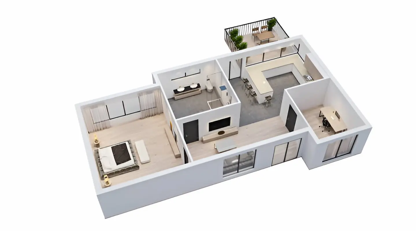
2. Floor Plans Drawing
The most widespread kinds of building drawings are linear drawings that outline the cross sections of a structure taken through a particular level. The major purpose of these blueprints is to visualize the whole building in detail, including windows, doors, walls, and many other essential features, such as layout. The floor plan drawing performs indispensable functions as it enables builders, engineers, and architects to grasp the structural details and spatial organization of the building. This will make the building design pleasing and practical to the eye.
3. Firefight Drawings
Safety design is paramount in today’s construction systems. Firefight drawings are also one of the essential parts of the building’s blueprint drawings that allocate points for water outlets, fire escapes, sandbags, fire hoses, or any fire safety equipment needed for overseeing the project.
4. Cross Section Drawings
Cross-section drawings allow architects to recognize different components of the infrastructure from a vertical perspective. This 2D illustration is perfect to provide a detailed overview of the visible and hidden components of the building. For instance, wall cross-section maps are another type of cross-section that can be used by contractors to visualize both sides of the wall.
5. Foundation Plans Drawing
Some of the most crucial features in construction drawings are the foundation and detailed ideation of the size, growth, and shape as well as various design elements of the skeleton. This depicts in detail how the ground pylon’s architecture is created to interact with the ground. It also provides a clear understanding of how this interaction guarantees the longevity and integrity of the building. So, foundation plan drawings are also vital for seamless construction.
6. Excavation Drawing
Excavation plan drawings play a considerable role in determining the depth, width, and length of the excavation for construction. Adding more to this, these drawings explain the overall scope of the excavation method, the scope of the excavation, and the removal of dirt. However, the critical techniques used for excavation are tunneling, trenching, wall shafts, and several more.
7. As-Built Drawings
As-built drawings are the ultimate records of the construction project and document the infrastructure as it was built, including any deviations or changes from the original plans. These drawings show a brief comparison between the original design and the finished constructed design. As-built maps are usually generated either during or after the construction.
8. Assembly Drawings
Assembly drawing plans illustrate in detail how different materials and components fit together during construction. These drawings are utilized in the construction industry to show a significant relationship between two structural components. Aside from this, assembly maps have different types of patterns and designs, like elevation, sectional, and 3-dimensional views.
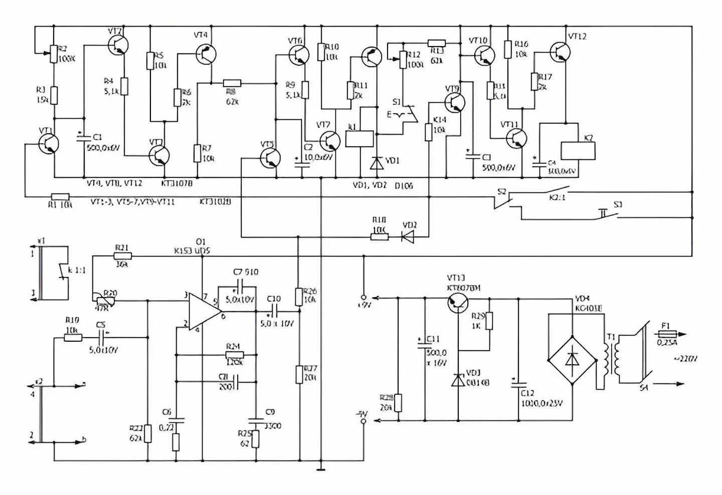
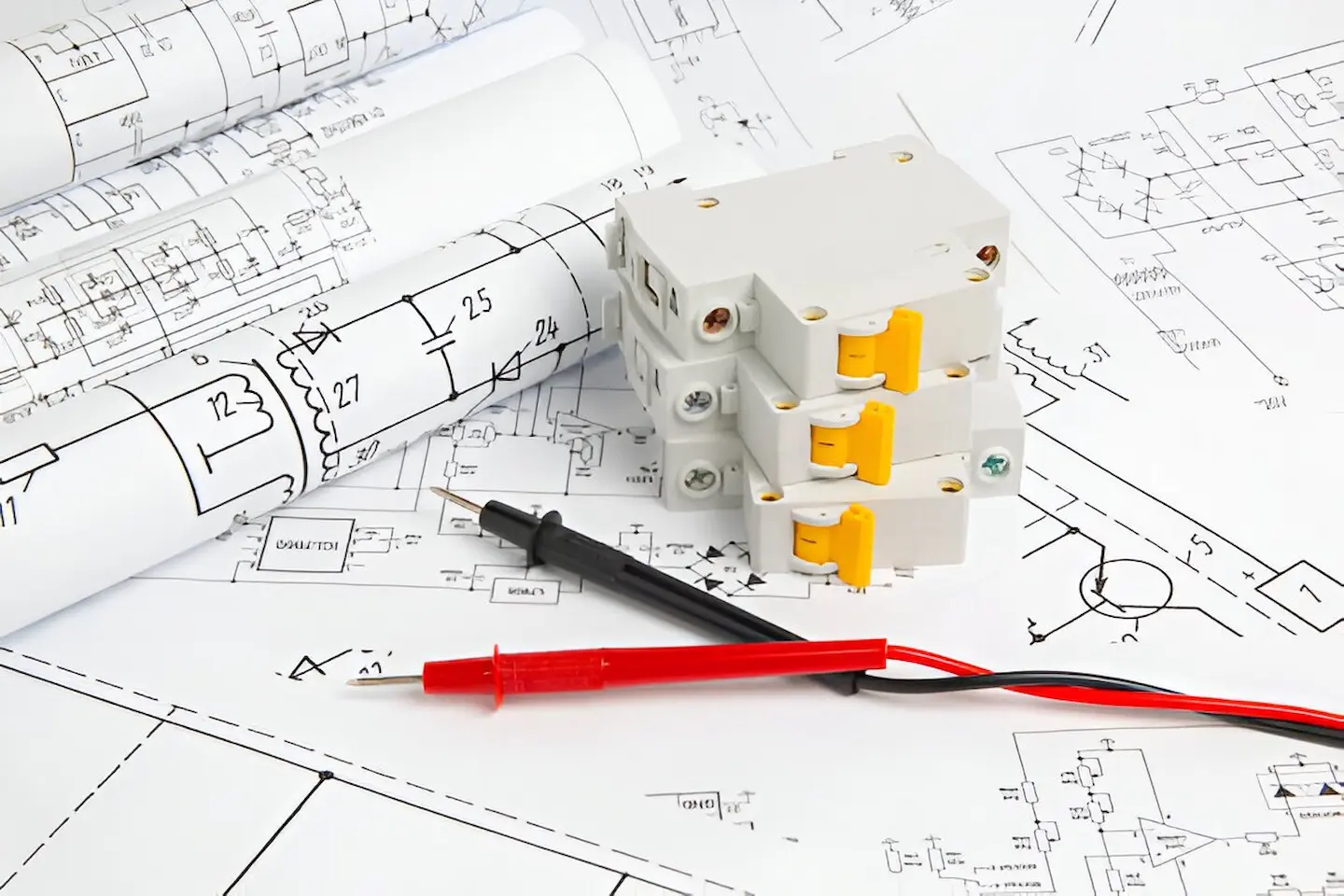
9. Electrical Drawings
Most commercial construction drawings or residential construction drawings need a functional outline of the number of fan fixtures, light fixtures, power outlets, etc. Besides, they also comprise the wiring details and pattern of the electrical load it can carry. However, common details included in electrical drawings are light fixture layout, cable tray layout, hazardous area classifications, generator and other equipment, lighting protection system, and many more.
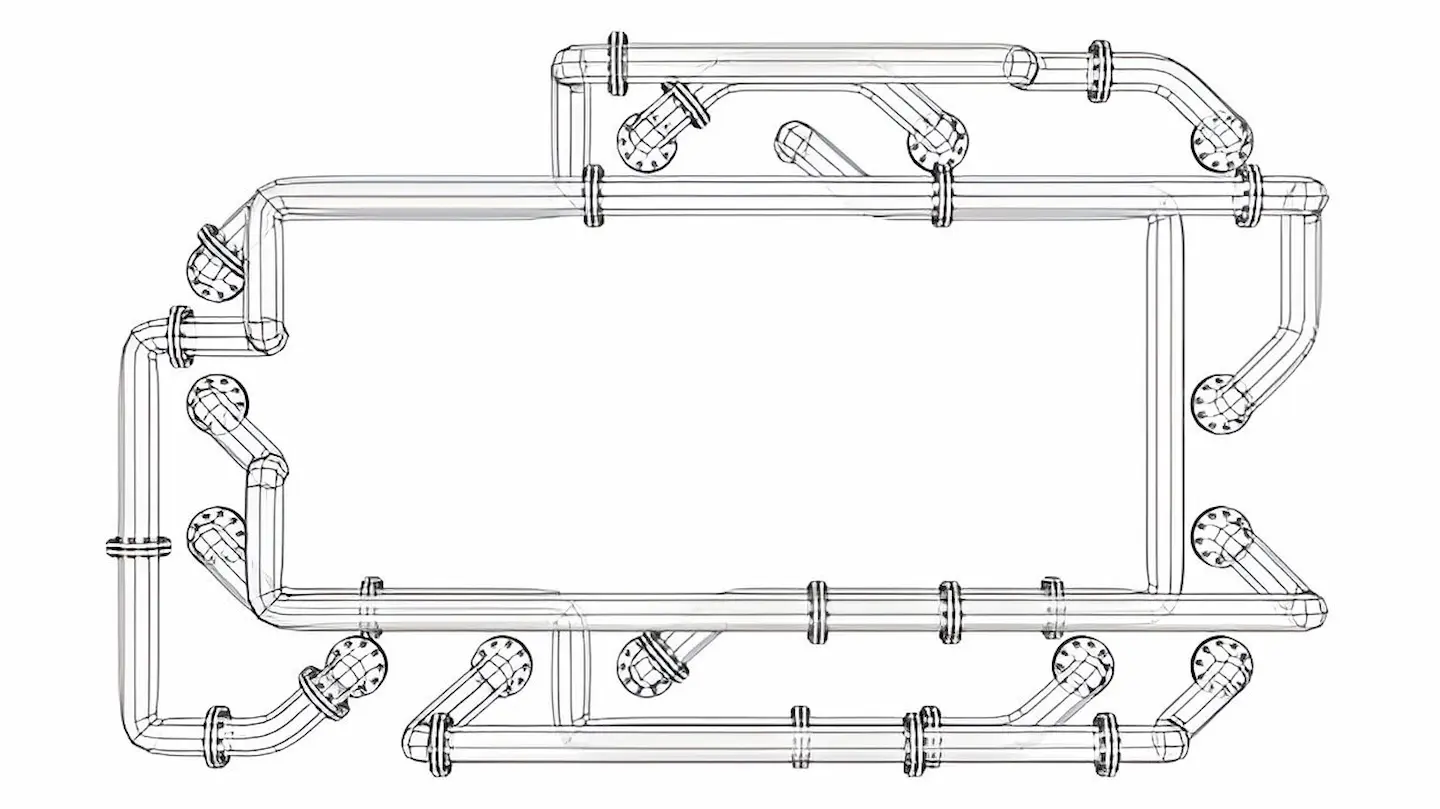
10. Plumbing Drawings
Just like electrical layouts, plumbing drawings are another crucial part of commercial or residential construction drawings that highlight the point where all the plumbing components need to be set up. Plumbing drawing plans mostly include water pipes, internal pipes, drainage pipes, material of pipes, tanks, sinks, taps, and the location and position of outlets and pipes.
11. Landscaping And Hardscaping Plans Drawing
Landscaping and hardscaping sketches extract all sorts of exquisite concepts. From the materials of pavements to the selection of plants and the overall concept of the space, you can learn a lot from them. This is a full-inclusive approach guaranteeing that every single piece finds a place and hence creates a comfortable and good-looking outdoor environment.
12. Reflected Ceiling Plans Drawing
Above all, reflected ceiling plans drawing issues a view of every room. For example, when you see the whole room from above and when you take off the room. Architects generate these drawings as detailed as possible to show the light fixtures, lighting elements as well as electrical networks. Briefly, these drawings give a complete picture of an interior for improved planning and execution of the whole project. This is how preparing a reflected ceiling plan map is critical.
Read More: A-Frame Home Design Plans
13. Roof Beam And Shuttering Layout
Roof beams are nothing but load-bearing elements that support the roofs and floor while supporting trusses, joists, and other roof elements to improve the building structure. In comparison, shuttering involves arranging the vertical space while supporting wet concrete making it gain the desired strength. So, shuttering and roof beam construction drawing plans depict the sections and reinforcement of detailed shuttering information and roof beam as well.
14. Wall Sections Drawing
Precise wall section drawings are a must for an in-depth understanding of the internal systems, such as plumbing, water supply, and electricity. This also gives contractors the ability to perceive which essential materials to be used for the process of construction. These illustrations retain an important role for contractors, giving the specified speed and precision of the building process.
15. Sections Drawing
The section drawings pinpoint one structure at a time by very precise and detailed sculpting from one level to the next, and, in return, the horizontal layout. Anyhow, this approach gives a more comprehensible explanation of a variety of single structural elements and concurrently illustrates how they work together to end up with a harmonious design for the infrastructure.
16. Finishing Drawing
Finished drawings include more detailed and finer building plans after the whole architectural and structural framework has been set up. These site plans are needed for the functional and aesthetic value of the building. However, these building drawings include details of plaster, woodwork, floor patterns, motifs and designs, false ceilings, paint colors and textures, and more.
17. Component Drawings
Component drawings provide comprehensive details and accurate dimensions of individual structural elements, such as footings, columns, beams, etc. Adding more to this, these drawing plans serve as a reference for the fabrication, manufacturing, or on-site construction of these components. Component drawings are also vital for the smooth completion of the construction.
18. Fabrication Drawings
Fabrication drawings are also known as shop drawings, which provide precise details, dimensions, and instructions from suppliers/manufacturers for prefabricated equipment, materials, or components offsite before delivery to the site of construction for installation. Aside from this, these drawing plans are created following design intent and project specifications.
19. Location Drawings
General arrangement drawings are called location drawings. These drawings are generated to show off the overall composition of the construction project. A location drawing will comprise crucial specifications of all components and the building that will be substantially developed as a part of their infrastructure project. Alternative plans, projections, elevations, sections, and alternative plans would be included in this type of building drawing design plan.
Read More: How To Become An Interior Designer
20. Installation Drawings
Multiple types of installations can be added to the infrastructure. For instance, ventilation, cooling, and heating systems are critical. So, a plan to help with all types of installations could be advantageous to the construction team and contractors. Such drawings are requisite for the most sophisticated structures, like control rooms and data centers.
21. Piping Spool Drawings
Plumbers use pipe spool drawings as a guideline for joining pipes divided into different sections, named spools. With the help of tees, an elbow, and several other components, plumbers connect spools on the construction site. Therefore, suppliers and manufacturers employ detailed spool information to produce fittings, pipes, flanges, spools, and more.
22. Environmental Plans
Ensuring environmental guidelines and management are appropriately followed is a significant part of building projects that can’t be overlooked. The ultimate purpose of these plans is to reduce environmental damage and some future negative impacts of the infrastructure project. It includes measures such as management of sedimentation and erosion, chemical disposal mechanisms, outlining environmental guideline compliance measures, and several more.
23. Perspective Drawings
Perspective drawing plans emphasize a spatial characteristic of an infrastructure while displaying its 3-dimensional volumes. Comprehensively, these are realistic digital visualizations of the whole under-construction building. However, vanishing point viewpoints are of various sizes and shapes. So, architects must also be aware of the general method of creating such plans.
24. Technical Drawings
Technical drawing designs have a broad meaning in the sense of construction. The primary purpose of these drawings is to depict the overall function of the building project. So, any drawing generated during the pre-construction stage, construction process, and after the construction can be considered technical drawings. They also help end your project on time.
25. Millwork Drawings
Millwork drawings are created for custom-made woodwork items. They are simply a set of pages where the shop will describe, specify, and display custom interior work. This may include suspended and cabinetry mantels. Such drawings show the specific lengths, widths, and materials that would be required for a millworker or carpenter to fabricate the different pieces.
26. Scale Drawings
Sometimes it becomes challenging to draw larger objects in their original size. For this reason, scale drawings are created to illustrate larger objects successfully. So, we can say that every architectural construction drawing is a form of scale drawing. For example, a floor layout is scaled at 1:100, a location plan at 1:1000, a site plan at 1:200, and so on. So, the readiness of the scale will accelerate substantially when the size of the object under construction increases.
27. Production Drawings
Production drawing plans are created to convey functional information to the engineers and workers on site. Furthermore, it describes the assembly of various parts, the dimensions, the materials, and other information needed during the process. This may also consist of an infographic and additional information on how to meet those essential set requirements.
28. Drainage Drawings
Drainage drawings show how water into and out of the infrastructure. If you maintain good drainage on your building project, it will assist in keeping future users of the structure healthy. Also, these kinds of drawing plans represent the precise sizes and placements of fixtures, including water tanks, pipes, drains, vents, pumps, sinks, bathtubs, faucets, closets, and more.
Read More: BIM And GIS Integration
29. Parametric Drawing
Parametric drawings are also an important part of building drawings that are generated using advanced parametric modeling software that enables the drawing views to automatically update upon changing design parameters, like dimensions. This ensures the next level of consistency.
30. Presentation Drawings
Presentation drawings are 3-dimensional models or highly detailed renderings used to not only communicate but also visualize the design intent for stakeholders, clients, and approving authorities. In short, they showcase the appearance and overall aesthetic qualities of the project.
31. Fire Protection Drawings
Fire protection drawings, also called safety plan drawings, include mapping the position of the firefighting equipment, the escape routes, as well as the design of the sprinkler system. This will help ensure compliance with regulations and building codes, also protecting property and life.
32. HVAC Drawings
HVAC drawings are termed mechanical drawings as well. They include crucial information on the heating and ventilation systems. Adding more to this, these drawings also cover the air conditioning patterns and layouts to be built within the structure. HVAC drawing plans give a better understanding of complicated mechanical systems, allowing builders to properly organize their construction process. The potential benefits of these drawings can’t be taken for granted.
33. Roof Slab Layouts
Roof slab layouts are a type of civil engineering drawings that showcase the exact dimensions of all the slabs needed for slants or roofs. In addition to this, these drawings are usually created over state-of-the-art AutoCAD software as they demand data and a higher level of precision too.
34. Column Layouts
These are the kinds of structural construction drawings that include the layouts of the way columns would be laid out. This makes it much easier for contractors to appropriately plan the building layout and begin the construction process by recognizing the distance and position between different columns across the floor. So, mapping such layouts is also very important.
35. Framing Plans Drawing
As the name shows, both roof and ground structures are delivered through the ceiling and flooring drawings, including the well-defined mounting of the rafters at their precise spacings. It indicates which types of joints and sizes of trusses, joists, and beams should go where to have excellent support and stability. Professional architects truly know how to prepare such drawings.
36. Detail Drawings
Detailed drawing plans are simply large-scale drawings focused on connections between various structural components. This also provides specific construction details needed for flawless project completion. Furthermore, these drawings also give magnified, in-depth information necessary for installation and assembly by showing dimensions, fasteners, and reinforcements.

37. Line Plan Drawing
This is a single-line representation of the room structure. The purpose of drawing these lines is to represent how different room configurations will be. It comprises room sizes and labeling and the location of the doors. This plan drawing shows how exactly the entire room will be laid out.
38. Survey Drawings
On top of all the above, the survey drawings indicate the existing conditions on the construction site depending on the detailed field survey data. They show site boundaries, topography, underground utilities, and other existing features paramount to planning new construction.
39. System Plans Drawing
System plan drawings are illustrations of the scheme that different low-voltage systems of the building will have, like that involving intercoms, security, and data and communication writing.
40. Isometric Drawing
Isometric drawings are a type of 3-dimensional parallel projection that depicts an object in an angled/oblique view. It shows three sides of the object with horizontal lines projecting at up to a 30-degree angle and vertical lines projecting at approximately a 30-degree angle.
41. Elevations Drawing
The renderings in this drawing plan are 2D replications of the facade of the building, imagining the visual nature of the structure from each angle. These views were developed to provide a comprehensive view of the exterior design before the construction of the actual building. Hence, elevation drawings enable a broad understanding and examination of the architectural idea.
42. Swimming Pool Design Drawing
Engineering such that the technical specifications and drawings must be met to execute a successful construction project. The drawing of a project comprising the construction of a water feature or a pool will state the shape, size, and kinds of materials to be used in its construction.

43. Parking Layouts Drawing
Such drawings show the area of each parking lot, like gates, lanes, and roads, for vehicle access to the building or a portion of the property. This differs from all other strategic ways of transport logistics because it includes considering accessibility, traffic flow, and also zoning regulations.
44. Signage Plans Drawing
The designs of the ads and signboards that would be put at the building, either around or on the building, help ensure that proper specifications are being followed and everything is well placed.
45. Design Drawings
Design drawings are conceptual construction drawings that are created by architects early in the design process to discover, develop, and communicate different design ideas to clients before moving to complex stages. They convey the overall form, character, and massing of the building.
Wrapping It Up
Construction drawings depict the evolution of the building through the project lifecycle. These plans represent how the construction project is handled from conceptual architectural structural details to the real stage of construction. Having all of the above-discussed building drawings in your hands has numerous benefits. Briefly, they serve as a kind of guideline for all builders.

