
What Is a Foundation Plan? Complete Guide for Builders & Drafters
People often ask, what is a foundation plan? At its core, it is nothing fancy, just a drawing, but it happens to be the one that shows how a building actually meets the ground. Open it up and you will see footings traced out like thick lines around the perimeter, walls marked where they’ll rise, and small boxes or circles where piers are meant to stand. It looks simple at first glance, almost like a sketch a student might doodle, yet every line has weight behind it.
So who actually uses this mysterious plan? More people than you think. Architects glance at it to check alignment with their floor layouts. Structural engineers pore over it for load calculations. Builders follow it like a treasure map when digging and pouring concrete. Even surveyors lean on it to make sure the set-out is true.
You might be asking yourself what is a foundation plan beyond the technical talk. That’s exactly what we’ll untangle here. We’ll break down the parts of a plan, walk through examples, explain how to read one without getting lost, explore the different foundation types, touch on permit checklists, and share how a professional CAD drafter makes the whole process a lot less stressful.
What Is A Foundation Plan?
If you are wondering what is a foundation plan, this blog is perfect for you! Here’s a simple foundation plan definition:
A foundation plan is the layout of walls, footings, piers, and every other detailing component that connects the structure with the ground.
It lays out dimensions and measurements that hold the entire project steady on the ground. Without it, nothing lines up.
Here’s the thing. This single sheet carries instructions for how the entire structure will be supported. It tells crews exactly where to dig, how deep to pour, where to place steel, and which points must carry the load. The foundation plan meaning isn’t hidden in jargon. It’s a translation of structural calculations into a language that builders can follow with boots on the ground.
Its purpose is blunt but critical. The plan directs the creation of footings and foundations so that the building’s weight doesn’t wander or tilt but flows cleanly down into the soil where it belongs.
What A Foundation Plan Typically Shows
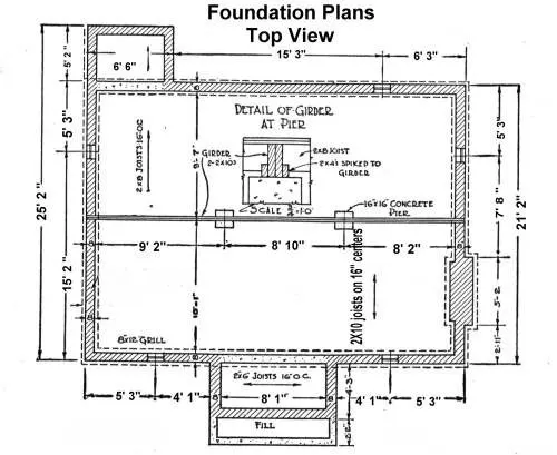
A foundation plan might look like a tangle of lines at first glance, but each mark has a job. These are the main components you’ll spot once your eye adjusts.
Footings
Footings are the base strips or blocks of concrete that spread the weight of the building into the soil. On a drawing, they appear as thick outlines hugging the perimeter or as isolated boxes under columns.
Definition: Footings on a foundation plan are the concrete bases shown with size callouts that support walls or columns. They may be continuous strips or isolated pads, depending on design.
Strip footings run in straight lines beneath walls, while isolated footings look like individual pads sitting beneath columns. Both are critical in preventing settlement and uneven loads.
Foundation Walls And Stem Walls
These walls sit on top of the footings and carry the structure above ground level. A drafter will mark their thickness, materials, and elevation notations right on the plan.
Definition: A foundation wall detail on a plan shows the location, thickness, and height notes for walls that connect the building to its footings.
Sometimes they’re full-height basement walls, other times short stem walls that bring the floor above grade. Either way, they’re labeled so builders know what to pour and where.
Piers, Columns, And Pad Footings
Where concentrated loads exist, you’ll see squares, circles, or crosses on the plan. These symbols point to piers or columns, each resting on a pad footing sized to handle the weight.
Definition: Piers and pad footings on a foundation plan are shown as labeled symbols that identify concentrated supports beneath columns or heavy points.
Their spacing and size notes prevent floors from sagging and keep roofs steady. Miss them on site, and the whole structure feels it.
Slab Details And Slab-On-Grade Notes
Not every building has a basement. Many rest directly on a slab. In these cases, the plan marks thickness, reinforcement, and sometimes control joints to handle shrinkage.
Definition: Slab details on a foundation plan are notes showing slab thickness, reinforcement patterns, and joint locations for concrete poured at ground level.
It may just look like a shaded rectangle, but the notes tell crews how to pour a slab that doesn’t crack the moment it dries.
Reinforcement And Rebar Notes
Concrete is strong in compression, weak in tension. That’s why plans carry a web of rebar notes: spacing, bar size, and placement.
Definition: Rebar notes on a foundation plan describe the type, size, and layout of reinforcing steel that strengthens concrete against tension.
You’ll see lines with hatch marks or abbreviations like #4 @ 12″ o.c., telling the crew exactly what to tie together before the concrete trucks arrive.
Dimensions, Gridlines, Levels, And Setting-Out Marks
A foundation drawing without dimensions is useless. The gridlines, level references, and distance notes keep everything tied to the architect’s floor plan.
Definition: Gridlines and dimensions on a foundation plan provide reference points and exact measurements that guide excavation and construction on site.
Surveyors use them like coordinates, checking that each footing is in the right spot before concrete is poured.
Drainage, Waterproofing, And Penetration Notes
Last but not least are the scribbles that save a house from dampness. Drain tiles, waterproof membranes, sump pits, and pipe sleeves often show up as notes or symbols tucked in the margins.
Definition: Drainage and waterproofing notes on a foundation plan mark where to install drains, membranes, sumps, and penetrations that keep water out of the structure.
They might look like afterthoughts on paper, but on site, they mean the difference between a dry basement and a flooded one.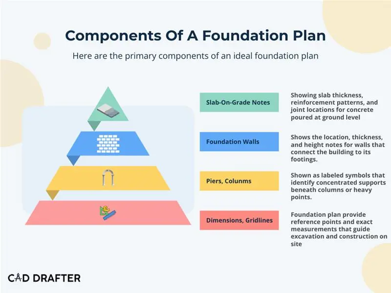
Foundation Plan Vs Basement Plan Vs Footing Plan
People often confuse these drawings because they sound similar, but they do very different jobs. Now that you know what is a foundation plan, let’s compare it with other drawings.
Quick Comparisons
- Foundation plan vs basement plan: A foundation plan shows the overall support system, while a basement plan shows the usable space layout below grade.
- Footing plan vs foundation plan: A footing plan zooms in on footing size and layout, while a foundation plan covers the entire structural base, including walls, slabs, and piers.
| Aspect | Foundation Plan | Basement Plan | Footing Plan |
| Purpose | Maps the structural base of the building | Shows room layout and features of basement level | Focuses only on the design and layout of footings |
| Typical Contents | Footings, foundation walls, piers, slabs, reinforcement notes, drainage details | Basement walls, stairs, doors, windows, mechanical rooms | Dimensions of footings, reinforcement details, locations under columns and walls |
| User | Structural engineers, architects, builders, surveyors | Architects, interior designers, contractors | Structural engineers, contractors, site crews |
| When Used | Early in construction to guide excavation and concrete work | When finishing or planning basement spaces | During excavation and footing placement before walls are built |
How To Read A Foundation Plan (Step-By-Step)
Hold the sheet up to the light, or zoom in until the grid lines look like a city map. Either way, it pays to slow down. Reading a foundation plan is partly pattern recognition and partly detective work. You will learn to spot the important clues, skip the noise, and check the things that actually matter on site. Below is a practical, no-nonsense walk-through on how to read a foundation plan, plus a compact glossary of the common symbols you will keep seeing.
1. Start With Scale And Orientation
Look for the scale note and the north arrow. If the scale is missing, you cannot trust the dimensions. Simple fact. If the plan uses a metric scale or an imperial one, convert in your head or on paper before you do anything else. Orientation tells you which way slopes and drains will run.
2. Read The Title Block And Notes
The title block hides essentials: project name, drawing number, revision history, and who stamped it. Notes often call out code references, soil reports, and any special instructions. Read them. Yes, every tiny block of text.
3. Find The Grid Lines And Reference Points
Grid lines are your coordinates. Use them to locate footings and piers. If something on site does not line up with the grid, stop and verify with the surveyor. Grid lines are how architects and engineers keep their stories in sync.
4. Identify Footings And Their Sizes
Footings are shown with size callouts. Find the width, depth references, and any reinforcement notes next to them. Is each footing continuous under a wall or isolated under a column? That makes a big difference in excavation and formwork.
5. Check Foundation Walls, Stem Walls And Slab Notes
Look for wall thickness, material tags, and elevation callouts. Slab notes tell you the thickness, section references, and control joint locations. These small notes keep a slab from cracking into a hairline nightmare.
6. Locate Piers, Columns And Pad Footings
Symbols like small squares or circles mark concentrated support points. Each symbol should have a tag or number that links to a schedule or detail. If the tag is missing, get clarification before pouring concrete.
7. Read Reinforcement And Rebar Instructions
A note, such as number four at twelve inches on center tells you bar size and spacing. Pay attention to lap lengths and covering requirements. Reinforcement is the invisible backbone that shows up only when something goes wrong.
8. Cross Check Sections And Detail Callouts
Follow the cut lines to find sections and enlarged details. The plan will rarely show depth and step-down information inline. Sections fill in the vertical story. Always match the plan view to its section view.
9. Verify Drainage, Penetrations And Waterproofing Notes
Drain tile, sump pits, pipe sleeves and waterproof membranes are often tucked into the margins. If the plan omits them, the permit reviewer will notice. Your future self will notice, too.
10. Final Sanity Checks Before Site Work Begins
Are all dimensions present and readable? Do the footing sizes line up with structural references? Are elevation levels consistent across sheets? If anything feels fuzzy, raise a query and get it recorded.
11. Glossary Of Common Symbols & Abbreviations
| Symbol / Abbreviation | Meaning |
| FTG or F | Footing, usually shown with width and sometimes depth callouts |
| FW or FND WALL | Foundation wall or stem wall, marked with thickness and elevation notes |
| P or Pier (with number tag) | Location of a pier, tag links to a schedule for size and reinforcement |
| SLAB + thickness note | Slab-on-grade with required thickness and joint information |
| #4 @ 12″ o.c. | Rebar notation showing bar size (#4) and spacing (12 inches on center) |
| Section cut symbol (A/1, B/3, etc.) | Refers to a section drawing that shows vertical or detailed information |
| Gridlines (A–D, 1–4, etc.) | Coordinate system used to locate elements on the site |
| SUMP or SUMP PIT | Location of the sump where water collects for drainage or pumping |
| MEMBRANE / WPRF | Waterproofing notes indicating membrane placement |
| SLEEVE Ø100 | Pipe or conduit sleeve through concrete, with diameter listed |
| Continuous Footing (CONT. FTG) | Strip footing running beneath a wall |
| EL 98.50 or ELEV | Elevation level for top of footing, slab, or wall relative to datum |
| Detail tag (e.g., 2/A-101) | Reference to an enlarged drawing of a component |
| Note callouts (1, 2, 3…) | Linked to general or special notes elsewhere on the sheet |
Types Of Foundations Shown On Plans (When To Expect Each)
Not every site calls for the same foundation. The plan you’re holding will reflect what the soil, the building load, and the budget demand. Here are the types of foundations you’ll most often see and the signs to recognize them on drawings.
Slab-On-Grade
A single, wide concrete slab poured directly at ground level. Plans usually shade the slab outline and note thickness, control joints, and reinforcement.
Definition: A slab-on-grade plan shows a flat concrete floor and foundation combined, with thickness and joint notes marked across the layout.
Crawlspace
A raised floor system sitting on short foundation walls or piers. Plans mark stem walls along the perimeter, sometimes with ventilation notes or access hatches.
Definition: A crawlspace foundation plan shows perimeter stem walls and piers that create a narrow space under the floor.
Basement Or Raft Foundation
Basement plans look like full-height foundation walls enclosing rooms below grade. Raft foundations, by contrast, show one thick slab covering the entire footprint, distributing loads evenly.
Definition: A basement or raft foundation plan shows thick foundation walls and slabs designed to carry both structural and habitable loads underground.
Strip Or Continuous Footing
Runs as a continuous strip beneath load-bearing walls. On plans, it appears as heavy lines hugging the wall layout, with dimension notes alongside.
Definition: A strip footing plan shows continuous concrete under walls, indicated by thick outlines and dimension callouts.
Isolated Footing
Square or rectangular pads sitting under individual columns or piers. Easy to spot as repeated boxes marked with size notes.
Definition: An isolated footing plan shows single pads beneath columns, drawn as small squares or rectangles with labeled dimensions.
Combined Footings
When two or more columns are close together, a rectangular footing may span both. Plans display them as elongated pads under multiple columns.
Definition: A combined footing plan shows a shared concrete base under two or more columns placed close together.
Pile Foundations
For weak soils or heavy loads, piles are driven deep into the ground. On plans, piles appear as clusters of small circles with caps tying them together.
Definition: A pile foundation plan shows groups of piles beneath a footing or slab, marked by circles and a pile cap outline.
Deciding Which Foundation Appears On Your Plan
- Soil conditions: Sandy soils may need deep piles, while firm clay often works with shallow footings.
- Load: Heavy or tall structures push toward raft or pile foundations.
- Water table: High groundwater makes basements tricky and favors slabs or piles.
- Budget: Slabs and shallow footings are typically cheaper, while piles and rafts add cost but solve risk.
The type drawn on your plan isn’t arbitrary. It reflects the dialogue between soil, structure, and budget.
Typical Workflows: Who Prepares Foundation Plans & How
A foundation plan doesn’t appear out of thin air. It passes through several hands before it becomes the sheet you see stamped and ready for permits. Each role nudges it along in a different way.
First, the structural engineer. They’re the ones running load calculations, checking soil reports, and deciding if the building needs deep piles or just a few strip footings. You won’t see their equations on the page, but every footing size, every rebar note, is their math translated into lines.
Then comes the architect. Their job is part traffic controller, part translator. They make sure the foundation layout lines up with the walls above, that stairwells don’t crash into footings, that chimneys have a place to land. Coordination may sound dull, but miss it and the whole building feels off.
And finally, the CAD drafter or BIM modeler. This is where the abstract ideas get drawn out, often in AutoCAD or Revit. The drafter isn’t just tracing; they’re producing a permit-ready foundation plan drawing, adding sections, notes, and details. Sometimes it’s a 2D CAD file, other times a fully linked 3D BIM model.
What should you expect in the end? Usually, a set: the main foundation plan (DWG or PDF), section cuts that show depths, enlarged footing or slab details, schedules listing columns or piles, and revision notes to track changes.
|
Best Practice? |
|
Always cross-check the drawings against the soil report and the engineer’s numbers. A CAD or BIM file looks clean on screen, but the ground doesn’t forgive mistakes. |
Permit Checklist For Foundation Plans
| Item | What Reviewers Look For |
| Scale | Clear scale note, legible when printed |
| Title Block | Project info, dates, revision history |
| Engineer’s Stamp | Signed and dated if required by jurisdiction |
| Elevation Notes | Levels tied to benchmarks or project datum |
| Dimensions | Footings, walls, piers, and slabs clearly dimensioned |
| Structural References | Linked to calculations or schedules |
| Soil Report Reference | Geotechnical data or soil bearing capacity |
| Drainage Notes | Sumps, waterproofing, perimeter drains, sleeves |
| Sections and Details | Depths, step-downs, and reinforcement details included |
Common Mistakes And How To Fix Them
| Mistake | Problem Caused | How to Correct It |
| Missing rebar notes | Unclear reinforcement → permit rejection | Always show size, spacing, and placement |
| Incorrect scale | Reviewers cannot verify dimensions | Check before plotting and printing |
| Omitted sections | Depth and step info lost | Add section cuts and cross-references |
| Unclear gridlines | Surveyors/architects can’t align | Match the grid with the architectural drawings |
| No elevation levels | Construction depth uncertain | Add top-of-footing and floor elevations |
| Drainage ignored | Risk of water damage or code fail | Note sumps, waterproofing, drains |
| Wrong footing dimensions | Unsafe load transfer | Cross-check with soil report and engineer’s calcs |
| No revision history | Confusion over the latest version | Mark all updates with dates/version tags |
| Generic notes | Reviewer confusion, delays | Use specific instructions, not “as required” |
| Stamp or signature missing | Immediate rejection | Ensure the licensed engineer signs and dates |
How Cad Drafter Helps
Producing a foundation plan is more than just drawing neat lines. At CAD Drafter, we translate the engineer’s numbers and the architect’s intent into a clear, permit-ready plan. That means every footing dimension, slab note, and elevation marker is checked, coordinated, and formatted the way local reviewers expect to see it.
We handle the details that matter: revisions when the engineer updates calculations, compliance with local codes, and the turnaround times builders need to stay on schedule. The result isn’t just a clean CAD drawing. It’s a package that moves smoothly through permitting and guides crews in the field without confusion.
Mini Case
One recent homeowner asked us to prepare the foundation plan for a compact single-family house. We coordinated directly with their structural engineer, drafted the plan in CAD with full footing and rebar details, and included the required notes for drainage and soil references. The permit reviewers approved it on the first submission, saving the client weeks of delay.
If you’re looking for a reliable foundation plan drafting service, we can help!
Request a permit review or Get a quote today.
FAQs
What is included in a foundation plan?
Think of it as the “map” for what goes under the building. A good foundation plan shows where the footings sit, how thick the walls are, the layout of piers, any slabs, rebar notes, plus drainage and elevation marks. Without these, the crew is basically guessing underground.
Who actually prepares a foundation plan?
Not a single person in isolation. An engineer decides the numbers, an architect makes sure the layout matches the building above, and a drafter (often in CAD or BIM) pulls it all together into a drawing that’s clear enough for permits and builders.
Can you use a foundation plan for permits?
Yes. In fact, in most places you’ll need it. Reviewers want to see footings, soil references, and sometimes an engineer’s stamp before they say “approved.” No foundation plan, no permit.
What’s the difference between a foundation plan and a footing plan?
The footing plan is a close-up! It’s all about the size, spacing, and reinforcement of the footings. A foundation plan is wider in scope, covering everything from walls to slabs to drainage. So footing plans live inside foundation plans, like a zoomed-in page.
How long does it usually take to get one prepared?
That depends on the size of the job. A small residential plan might be done in just a few days. A larger commercial building? Add a week or two, especially if revisions keep bouncing between the engineer and the architect.
What are little footing symbols and what do they mean?
They’re shorthand for what’s happening under the ground. A square might show an isolated footing, a rectangle could mean a strip footing, and each symbol usually ties back to a schedule with exact dimensions.
Do I really need a soil report for a foundation plan?
Almost always, yes. The soil report tells the engineer what the ground can handle. Without it, footing sizes are just educated guesses, and permit reviewers don’t gamble.
How much does a foundation plan cost?
There’s no flat number. Costs shift with project complexity, local requirements, and how many revisions the design team needs. A small house may be relatively inexpensive, while a commercial foundation plan can be a significant budget line. The only honest answer: get a quote for your project.
Ready To Build On Solid Ground?
After knowing what is a foundation plan, it is not wrong to say that every structure begins here. The lines and notes on a foundation plan may look simple, but they decide how your building meets the earth. Skip details and you risk delays, failed permits, or worse. Get it right the first time, and everything above runs smoother.
That’s what we focus on at CAD Drafter. We take the engineer’s design, match it with code requirements, and produce a set of drawings that reviewers can read without hesitation. Expect clear footing sizes, accurate elevations, drainage and rebar spelled out instead of buried in vague notes. And when the city stamps it approved on the first review, that’s the payoff fo us!
If your project is about to break ground and you still don’t have a permit-ready foundation plan, let’s fix that now.