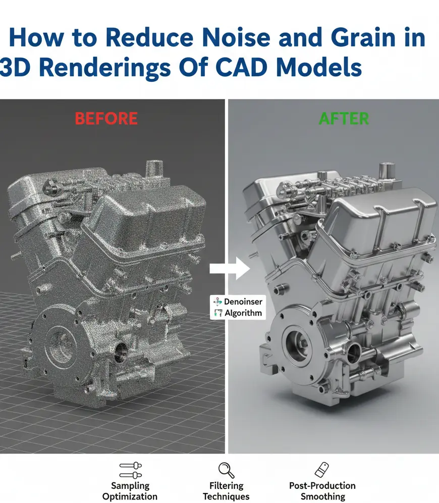
How to Reduce Noise and Grain in 3D Renderings Of CAD Models
In the 2026 CAD-world, grain isn’t a stylistic flaw. It’s a credibility problem. A noisy render quietly tells the client you lost control somewhere, of light, of math, or of time. The software does not matter. Whether the model came out of SolidWorks, Rhino, or Fusion, once grain creeps into metallic edges or pools in shadowed corners, realism just vanishes. This is also why many teams struggle with renders that technically look correct but still feel “off” compared to real-world finishes, a gap explored further in why 3D CAD renders don’t match real materials.
And expectations keep rising, fast! As 2026 started, GPU path tracers and AI denoisers are no longer advanced; they’re assumed. Clients expect renders that read like photographs, not previews. Yet many experienced teams still fight speckled shadows and crawling reflections. Not because the tools are weak. Because the problem is misunderstood.
Cleaning a render isn’t about brute force. We will highlight all the hidden tricks to reduce noise and grain in the 3D rendering of CAD models. By the end of this guide, you’ll be able to create renderings that stay clash-free and ensure precise fabrication.
Why Do Renders Get Noisy?
Before we can fix noise, we must understand its origin. In modern Path Tracing (the algorithm used by most high-end renderers), the software shoots “rays” from the camera into the scene. These rays bounce off surfaces to collect light and color data.
Noise occurs when the software doesn’t have enough data (samples) to calculate the color of a specific pixel accurately. If one ray hits a bright light and the next ray hits a dark corner, the software guesses the average, resulting in a grainy, speckled appearance.
The Primary Culprits of Render Grain:
Undersampling: The most common cause. Simply put, you aren’t giving the engine enough time to clean the image.
Poor Lighting Geometry: Large light sources are easy to sample; tiny, high-intensity pin lights (like LEDs) are a nightmare for ray-tracers.
Material Complexity: Rough metals (brushed aluminum) and refractive materials (glass) require significantly more bounces to resolve.
Indirect Illumination (Global Illumination): Light that has bounced multiple times carries less energy and more uncertainty, leading to splotchy shadows.

1. Master Sampling Strategy
The most direct way to reduce noise is to increase the Sample Count. However, doubling your samples often quadruples your render time. The key is Adaptive Sampling.
The Threshold Secret
Most modern engines (like V-Ray and Arnold) use a Noise Threshold (sometimes called Adaptive Amount).
The Logic: Instead of giving every pixel 1,000 samples, the software analyzes the image. If a clear sky is already clean at 50 samples, it stops. If a dark corner is still noisy at 500 samples, it keeps going.
The Fix: For a production-quality render, set your Noise Threshold to 0.005 or 0.01. If you are still seeing grain in the shadows, drop it to 0.002. However, be prepared for a significant jump in render time.
Sub-Sampling vs. Global Sampling
In 2026, engines have moved toward Universal Settings, but granular control still exists in many CAD-specific tools.
Light Samples: If your shadows look grainy but your textures look sharp, increase the samples on the Light Source itself rather than the global render settings.
Specular Samples: If the highlights on your CAD model’s chrome or glass parts are noisy, specifically increase the Glossy or Specular sampling.
2. Optimizing CAD Geometry for Light Bounces
A noisy render often starts long before lighting or sampling. It starts in the model. Engineering-grade CAD files are built to manufacture parts, not to behave nicely under ray tracing. They hide things. Internal faces no one will ever see. Surfaces stacked on top of each other. Gaps so small they feel harmless. To a renderer, they’re chaos. Light hits those areas and hesitates.
The Overlap Trap
When two surfaces live in the same space, same coordinates, same depth, the renderer can’t commit. One frame, it chooses surface A. The next surface, B. In animation, that becomes flicker. In stills, it shows up as dirty specks and inexplicable dark noise.
The Fix
Clean the model before it leaves CAD. Run a geometry audit in SolidWorks, Rhino, or Fusion 360. Merge bodies that overlap. Delete internal faces that serve no visual purpose. Check your normals. Everything should point outward, no exceptions. A clean mesh gives light a clear path, and the noise drops with it.
The Sharp Edge Problem
Mathematically perfect 90-degree edges in CAD are a major source of specular aliasing (tiny white dots known as Fireflies).
The Fix: Apply a 0.5mm Fillet to every visible edge. A rounded edge allows the light to create a specular highlight (a thin line of light), which gives the renderer a clear target to sample. This single change can reduce highlight noise by up to 30%.
3. The Power of AI Denoising (The 2026 Standard)
Denoising used to be a last resort. A softening pass. Something you apologized for.
That era is gone. By 2026, AI-driven denoisers will no longer be optional add-ons; they’re baked into serious workflows. Used correctly, they cut render times in half. Sometimes more. And they do it without turning your materials into wax.
OptiX vs. OIDN
They solve the same problem. They behave very differently.
NVIDIA OptiX
Fast. Aggressive. Perfect for look-dev. It leans on GPU tensor cores to clean images almost instantly, which makes it ideal while you’re tweaking lights or dialing materials. You trade a little texture fidelity for speed, and that’s usually fine at this stage.
Intel Open Image Denoise (OIDN)
Slower. Smarter. Better for finals. OIDN is conservative by design. It protects fine detail (wood grain, fabric weave, subtle bump transitions) where OptiX sometimes smears them away. When image quality matters more than feedback speed, OIDN wins.
The Pass Strategy (Where Pros Gain Control)
Never denoise everything at once. Render separate AOVs. This includes reflection, refraction, and diffusion. Each behaves differently under AI, and reflections are almost always the weakest link.
Expert Tip
Denoisers hate glossy chaos. Clean the reflection pass on its own in post using tools like Topaz or Neat Video. You’ll smooth out the noisy glare without blunting edges or flattening your CAD geometry. Clean where it’s needed. Leave the rest alone.
Learn the secrets to reduce noise in 3D renders
4. Lighting: Bigger is (Usually) Better
The physics of light dictate that a small, intense light source is much harder to “calculate” than a large, soft one.
1. Swap Point Lights for Area Lights
Point lights are mathematical dots. They create hard, noisy shadows. In 2026, always use Area Lights (Rectangles or Discs). By giving the light a physical size, you “spread” the samples, creating smoother gradients and less grain.
2. The Light Tree Advantage
If your CAD scene has dozens of lights, enable the Light Tree. it is available in Blender 5.0+, V-Ray, and Arnold. This algorithm prioritizes the lights closest to the camera. As a result, it reduces the statistical noise caused by distant, unimportant light sources.
3. Use Portals for Interiors
If you are rendering a CAD model inside a room, use Light Portals in the windows. These don’t create light; they guide the rays from the outside HDRI environment directly into the room, reducing the noise caused by rays getting lost in the scene.
5. Material Math: Reducing Complexity
High-gloss materials with high Roughness values are the #1 source of grain in CAD rendering.
The Roughness Threshold
When a material has a roughness value between 0.2 and 0.5, the rays are scattered in thousands of directions.
The Fix: If a material looks grainy, try reducing the roughness slightly or increasing the Specular Samples for that specific material.
The Firefly Killer: If you see bright, single-pixel dots (Fireflies), use the Clamp setting in your renderer. Setting a Max Ray Intensity of 10.0 or 20.0 will cut off those rogue high-energy rays that cause the speckles, without significantly darkening the overall scene. In many cases, the noise problem is amplified by poor UVs and shader setup, which overlap with the most common texture mapping mistakes that ruin 3D renders.
6. Depth of Field
One of the sneakiest ways to handle noise in a complex CAD assembly is to use Depth of Field (DoF) strategically. A camera lens can’t keep everything in focus at once. By mimicking this in your render, you achieve two things. One, you guide the viewer’s eye to the most important part of your model, and second, you blur out the noise in the background.
The Physics of Blur: Noise is much less noticeable in out-of-focus areas because the pixels are naturally blended.
The Pro Move: Instead of trying to get a 100% clean render across the entire frame, focus your sampling power on the Hero part of the CAD model (e.g., the engine block or the watch face). Let the peripheral components have a soft, cinematic blur.
The Catch: Beware of Bokeh Noise. If your F-stop is too low, the blurry highlights can become splotchy. Always ensure your Sub-Pixel Mapping is turned on to keep those blurry circles smooth and creamy.
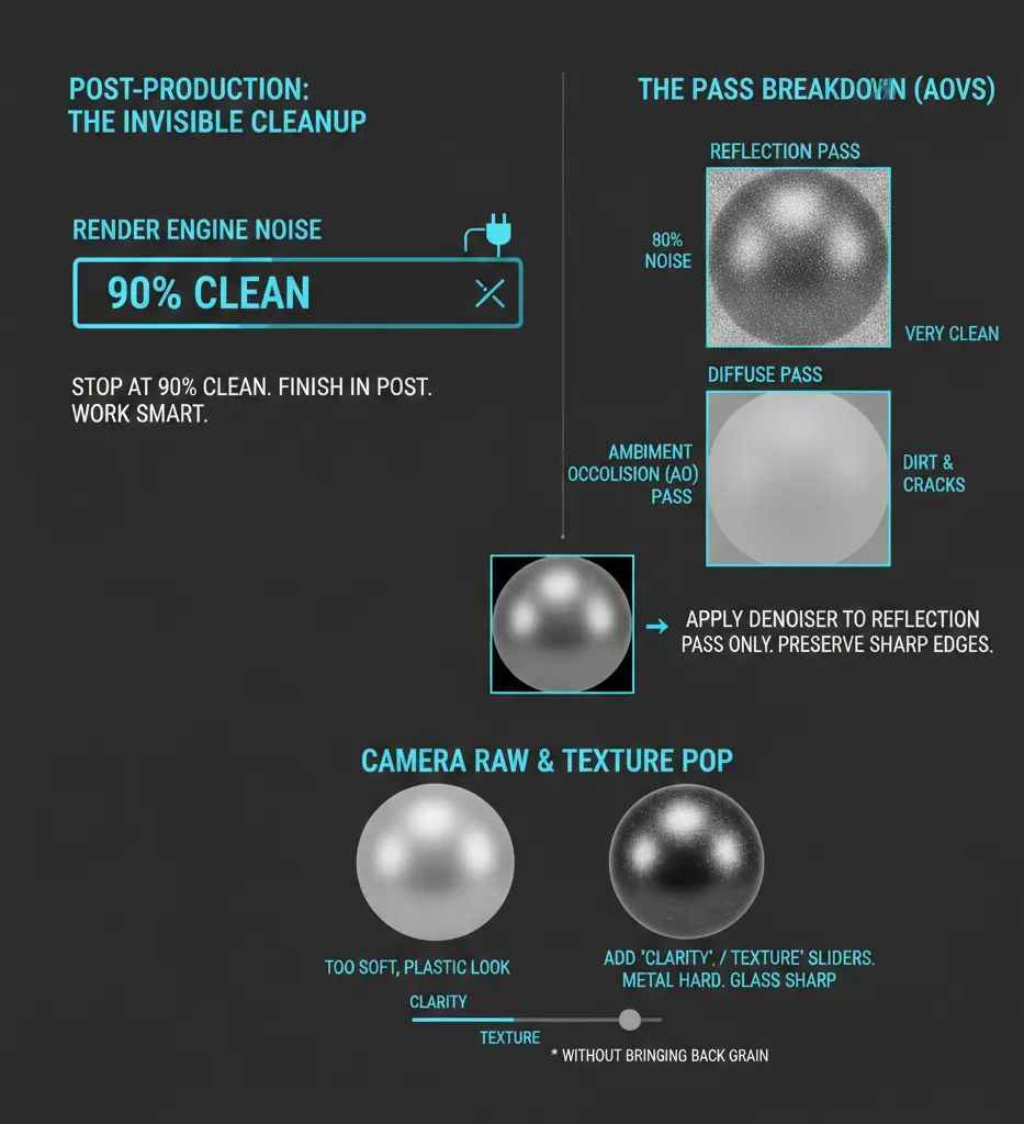
7. Post-Production: The Invisible Cleanup
If you are waiting for your render engine to reach 0% noise, you are wasting electricity. The most efficient pros stop their renders at 90% clean and finish the job in post-production. Clean, noise-free renders also play a critical role when visuals are used downstream for manufacturing references, especially when preparing CAD drawings for CNC fabrication. This isn’t cheating; it’s working smart.
The Pass Breakdown (AOVs)
When you render, don’t just save a single JPG. Save a Multilayer EXR with different passes:
Reflection Pass: This is usually where 80% of your noise lives.
Diffuse Pass: This is usually very clean.
Ambient Occlusion (AO) Pass: This defines the dirt and shadows in the cracks.
By separating these, you can apply a heavy denoiser only to the Reflection pass in Photoshop or After Effects. This preserves the sharp, crisp edges of your CAD geometry in the Diffuse pass while smoothing out the grainy reflections.
Camera Raw & Texture Pop
Sometimes, denoising makes a render look too soft, almost like it’s made of plastic.
The Fix: After denoising, use the “Clarity” or “Texture” sliders in Camera Raw filters. This adds a micro-contrast back into the image, making the metal look hard and the glass look sharp again without bringing back the original grain.
8. Hardware Optimization: Don’t Let Your PC Be the Bottleneck
In 2026, the debate between CPU vs. GPU rendering is largely settled for CAD visuals: GPU is king for speed, but CPU is still the master of clean shadows.
VRAM Management: If your CAD model is massive (e.g., a full factory layout), your GPU might run out of VRAM. When this happens, the render slows down, and noise levels skyrocket because the computer is struggling to swap data.
The Fix: Simplify your instance geometry. If you have 1,000 bolts in your CAD model, ensure they are Instances, not unique meshes. This keeps your VRAM light and your render rays fast.
Thermal Throttling: It sounds basic, but a hot GPU produces more computation errors, which can manifest as fireflies. Ensure your workstation is well-ventilated during those overnight render marathons. For many firms, achieving this balance consistently comes down to workflow decisions as well, including whether in-house or outsourced BIM modeling offers better control over visualization quality.
9. The Firefly Exterminator: Advanced Clamping
We’ve mentioned fireflies (those annoying white dots), but let’s talk about the “Nuclear Option” for getting rid of them: Max Ray Intensity (Clamping).
In a perfect simulation, light can be infinitely bright. But your monitor can only show White. Fireflies happen when a ray hits a corner and calculates a brightness value of 1,000,000%.
The Setting: Look for Clamp Output or Max Sub-Pixel Intensity.
The Magic Number: Set your “Clamp” to 1.5 or 2.0. This tells the software: If a ray is brighter than 2.0, just pretend it’s 2.0.
The Result: Your fireflies disappear instantly. The downside? Your highlights might lose a tiny bit of sparkle, but for a clean CAD product shot, it’s a trade-off you should make 9 times out of 10.
10. Animation Grain: The Flicker Nightmare
If you are rendering a video of your CAD model, noise is even more dangerous because it crawls and flickersfrom frame to frame.
The Temporal Denoiser: Standard denoisers look at one frame at a time. Temporal denoisers (like the ones in Nuke or DaVinci Resolve) look at the frames before and after.
The Rule of 2x: For animation, you generally need twice the samples of a still frame. If a still looks good at 500 samples, your animation will likely need 1,000 to prevent that “dancing grain” effect on metallic surfaces.
The Zero-Noise Table
Before you hit Render and go to bed, run through this table to ensure you aren’t coming back to a bucket of sand in the morning.
| Category | The Catch | The Fix |
| Geometry | Are there overlapping faces? | Use “Delete Duplicate” in CAD. |
| Edges | Are they razor-sharp? | Add a 0.5mm bevel/fillet. |
| Lights | Using tiny “Point” lights? | Switch to Area Lights or HDRI. |
| Clamping | Seeing Fireflies? | Set Max Ray Intensity to 2.0. |
| Denoising | Losing texture detail? | Switch to Intel OIDN or lower the strength. |
| Samples | Shadows look splotchy? | Increase the Noise Threshold to 0.005. |
The Bottom Line
At the end of the day, reducing noise in your CAD renders is about intent. A grainy render looks like a mistake; a clean render looks like a photograph. By mastering the balance between Adaptive Sampling, AI Denoising, and Strategic Lighting, you turn your CAD models into persuasive assets that win clients and close deals.
Don’t let a layer of digital dust mask your hard work in SolidWorks or Rhino. Clean it up, clamp those rays, and let your design shine.
Frequently Asked Questions (FAQs)
1. Why does my render look clean in the preview but grainy in the final?
Usually, this is because your Interactive settings use a different denoiser (like OptiX) than your Production settings. Ensure your production samples are at least 4x higher than your preview samples.
2. Can I just Photoshop out the grain?
To an extent, yes. Using the Reduce Noise filter in Photoshop works for minor grain, but it can’t fix splotchy Global Illumination. It’s always better to get it 90% right in the render engine.
3. Does more RAM make renders cleaner?
Not directly. RAM allows you to render larger and more complex scenes without crashing. VRAM (on your GPU) and Clock Speed (on your CPU) are what determine how fast those samples get cleaned up.
4. Why is glass always the noisiest material?
Glass requires Refraction Bounces. Most renderers default to 8 bounces. For complex glass, you need 16 or 32 bounces to allow the light to fully pass through and come out the other side without getting lost and creating noise.
5. Is there a magic button for no noise?
In 2026, NVIDIA’s DLSS 3.5 (Ray Reconstruction) is the closest thing we have. It uses AI to reconstruct the light rays literally. If your software supports it, turn it on.