How to Read Construction Drawings: A Step-by-Step Guide for Contractors & New Hires
Construction drawings are the detailed plans. They show how a building should actually come together, including every wall, wire, pipe, and bolt. In simple terms, they’re the visual instructions that turn an architect’s idea into something solid you can walk through.
On site, these drawings are everything. They tell you where to dig, where to cut, and what to connect. So, if you miss one note and you might pour a footing in the wrong place. Moreover, ignoring the importance of drawings can lead to hanging a door that never closes properly. Sounds small, but those slips add up.
Industry research has shown that mistakes and unclear drawings eat away roughly 12.4% of total project costs. That’s billions lost each year: money that could’ve built something better.
To reduce these losses, it becomes vital to understand the drawings in the best way possible. That’s how developers and project managers ensure precision and accuracy. This blog is your guide to assessing every type of construction drawing without any hassle.
Who This Guide Is For
This isn’t just another read-and-forget article. This is for the people who actually build things. Here are the people who will find it befitting:
- Contractors and foremen who make the calls on site.
- New hires are learning how the plans translate to work.
- Site engineers who check grades, levels, and layouts.
- CAD and BIM technicians who turn designs into usable documents.
- Subcontractors who need to fit their work into someone else’s plan.
Here’s what you will be able to do after reading
- Read plans with less guesswork.
- Spot critical notes and avoid common mistakes.
- Cut rework and save time on the job.
- Coordinate changes so trades don’t clash.
- Verify accuracy before anything is ordered or built.
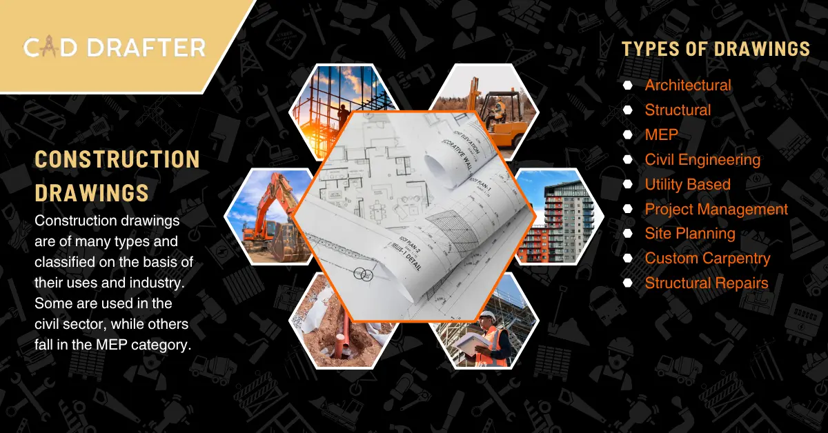
Types Of Construction Drawings (What Each Sheet Does)
Alright. Let’s slow this down and look at the set like a crew would on site. There’s an order. A logic. Once you learn it, you’ll flip to the right sheet without guessing.
Typical sheet order you’ll see (common practice):
0 = General / Cover
1 = Plans
2 = Elevations
3 = Sections
4 = Large scale / Areas
5 = Details
6 = Schedules
9 = 3D / Isometrics / Special views
Think of it as: start wide, then zoom in!
What Each Type Actually Shows (Practical Breakdown)
Architectural
- Floor plans, room layouts, door and window locations.
- Finish callouts: floor finishes, paint, ceiling types.
- Notes about dimensions, door tags (D-101, etc.), and room names.
- Useful on-site when you need to place partitions, set out openings, or confirm finishes.
Structural
- Foundation plans, footing sizes, column and beam locations.
- Rebar schedules, slab thickness, and connection notes.
- Shows load paths and clearances. If a wall is “architectural” but sits on a structural beam, the structural sheet tells you how to build it so it carries weight.
MEP
- HVAC layouts, duct runs and diffusers, piping risers, plumbing fixture locations, conduit and panel schedules.
- Riser diagrams and equipment schedules (like boiler or AHU tags).
- Critical for coordination. MEP often needs space inside ceilings, shafts, and under floors.
Civil / Site
- Grading plans, contours, drainage, utility routing, curb and paving layouts.
- Shows finished ground levels, invert elevations for pipes, and set out for curbs or roads.
- First sheets used for site work and any excavation layout.
Details & Large Scale
- Enlarged drawings for tricky stuff: window jambs, stair construction, waterproofing at joints, flashing details.
- Large-scale plans (1:10, 1:5 or similar) for assemblies that need exact measurement and sequence.
Schedules
- Door schedule (size, frame, hardware), window schedule, finish schedule, lighting and panel schedules.
- These are lists that link tags on the drawings to specific products or sets of requirements.
Real-World Tips
- Always check the cover sheet for the sheet index. It tells you where to look.
- If a door callout is D-202 on the plan, jump to the door schedule, not a random detail.
- When a section cut appears on a plan, go read the section. Details live in the sections and detail sheets.
- Never assume one discipline’s sheet overrides another. They complement each other.
Always Do Cross-Discipline Coordination
The architect might show the doorway. Structural may show the beam above. MEP wants to run a duct through that space. If you act on just one drawing, you’ll clash. Always check at least two other relevant sheets: structural and MEP vs architectural. Mark conflicts. Raise an RFI if something can’t be built as drawn.
Anatomy Of A Drawing Sheet | What To Read First
Every sheet in a drawing set has its own rhythm. Before you start chasing lines and dimensions, take a minute to look at the page like a story and not a maze. The information you need most isn’t always at the center. It’s in the corners. Let’s walk through it.
1. The Title Block
Always start here. It’s usually parked along the right or bottom edge of the sheet. You’ll find the project name, sheet number, scale, drawing title, date, and the designer or consultant’s name.
This block is your map key. It tells you which sheet you’re holding and how it fits into the full set. If you skip this, you could be reading a basement plan while standing on the roof.
Also check the scale before you do anything else. A line that looks ten feet at 1/8″ = 1′-0″ might actually be half that size on a detail sheet.
2. Revision Block And Revision Clouds
Look for a small box, often near the title block. That’s the revision block. It lists the date and number of every change made since the first issue. On the drawing itself, you’ll see revision clouds
Why this matters: if you’re building from an outdated version, you could install something that no longer matches the design. Always confirm the revision letter or number matches the current issue before starting work.
3. General Notes And Specification References
Up in the corners or across the side margin, you’ll find general notes. These are the designer’s direct messages to the field. They mention standards, materials, and installation methods.
They often reference the spec book (“see spec section 09 29 00 for gypsum board”). Don’t ignore those numbers. The spec is the rulebook. The drawing tells you where something goes; the spec tells you how it must perform.
4. Legends And Symbols
Construction drawings use symbols as a shorthand language. A simple circle with “E1” might mean an electrical outlet, while a triangle could mark a diffuser. Somewhere on the sheet (or in the front pages), you’ll find the legend explaining what each symbol means.
Spend time here. Once you learn the symbols, the whole set starts to speak to you. If something doesn’t match the legend, flag it. It might be a drafting error or a symbol from another discipline’s standard.
Symbols, Abbreviations & Conventions
Every trade speaks its own dialect, and construction drawings are no different. They use symbols and short codes so information fits neatly on paper. Once you learn that language, the drawings start to talk back.
Let’s break it down.
Common Symbol Families:
- Doors and windows: arcs that swing open, rectangles showing glass, tags like D-101 or W-05.
- Electrical: outlets, switches, lighting symbols, panel tags, and circuit references.
- Plumbing: lines for supply and waste, fixture icons, valves, and cleanouts.
- HVAC: diffusers, grilles, ducts, thermostats, often marked with triangles or square icons.
- Other trades: sprinklers, fire alarms, low-voltage lines, security devices, all have their own icons.
You’ll find a legend explaining each one, usually near the start of the set. Keep that close. Better yet, make a cheat sheet for your crew. Nothing fancy, just a quick note taped near your workstation so nobody confuses a symbol for a smoke detector with one for a ceiling speaker. Abbreviations You’ll See Everywhere
Drawings love abbreviations. Here are some you’ll spot daily:
- Typ.= typical (used in similar conditions)
- O.C. = on center (distance between identical elements)
- NTS = not to scale
- CL = center line
- FF = finished floor
- ± = plus or minus, small tolerance
- Ø = diameter
Scales & Dimensioning (Practical Decoding)
This part separates the careful from the careless. Every line on a drawing represents a real-world distance, but only if you read the scale correctly.
Common Scales:
- Imperial: 1/8″ = 1′-0″ for large floor plans; 1/4″ = 1′-0″ for tighter interior layouts; 1/2″ = 1′-0″ for details.
- Metric: 1:100 or 1:50 for general plans; 1:20 or 1:10 for close-ups.
The scale tells you how the drawing translates to reality. Always check it in the title block first. If the sheet says NTS (Not to Scale), don’t try to measure and rely on written dimensions only.
If no scale is listed, compare a known element, like a door (usually around 900 mm or 3 feet wide), to estimate proportion. In CAD or a digital PDF, use the measure tool, but confirm one known dimension before trusting the rest.
How Dimensions Work
Drawings show different layers of measurement:
- Overall dimensions: total width or length of an area.
- Detailed dimensions: individual components like door openings or stud spacing.
- Cumulative dimensions: a chain of measurements that add up to the overall length.
- Datums or baselines: fixed reference lines used to align multiple sheets.
- Tolerance notes: tell you how precise it must be; a “±10 mm” note means a small variation allowed.
|
Golden Rule |
|
Never add up dimensions from the sheet to “check” a measurement. Use what’s written. If numbers don’t match, ask and don’t assume |
Line Types, Weights & Hatching
Every drawing speaks in lines before it ever says a word. Some are bold, some whisper-thin. Each has a purpose. Once you notice it, you’ll start to see the logic hidden in the page.
Let’s start with line weight.
Thicker lines usually mark the things that have been cut through in a plan or section. Think of it as slicing the building open and bolding the edges where the knife passes. Medium lines outline visible objects: doors, windows, fixtures, furniture. Thin lines? Those show what’s behind or above, like ceiling grids, overhead beams, or items in the background.
Then there are line types. A solid line means something you can see. A dashed or dotted line hints at something hidden, a pipe below the floor or a beam above your head. Center lines run long-short-long; they mark symmetry or exact alignment points. When you know how to read them, you can tell depth just from ink.
Now look at the hatching.
That’s the pattern filling the shapes. It’s not decoration. Each hatch tells you what the material is. Crosshatch for steel or metal. Small dots for concrete. Brick patterns for masonry. Light diagonal lines for insulation. Every discipline has its own legend for this. In sections, the hatch shows the layers of a wall or floor. You can see how concrete meets rebar, or how a slab sits on insulation.
Send Plans And Get A Quote!
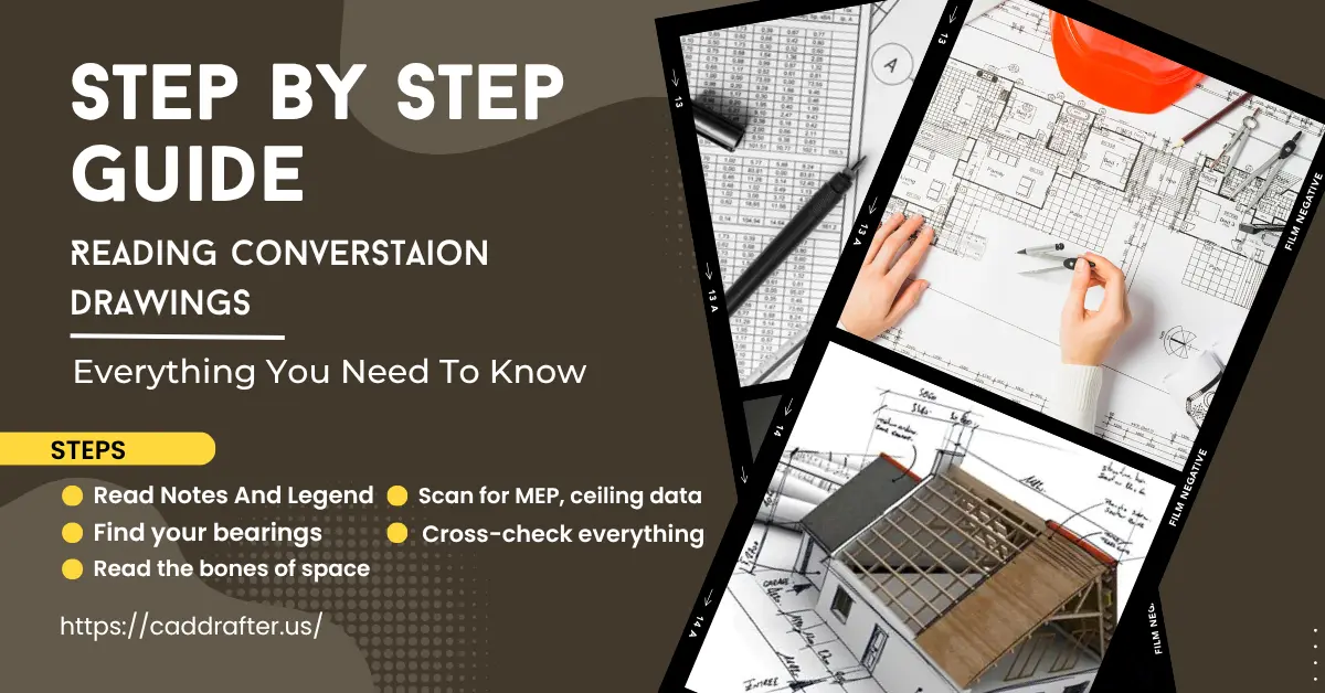
Step-By-Step: How To Read A Floor Plan (Practical Workflow)
A floor plan looks simple (lines, boxes, some text but every inch of it carries meaning. If you rush, you’ll miss the clues that make the drawing readable. Slow down, breathe, and follow this rhythm.
Step 1: Start At The Edges
Open the sheet. Don’t dive straight into the lines yet. Look first at the title block, revision number, and sheet index. Make sure you’re holding the latest issue. It’s painful to discover halfway through a job that you built from Sheet A1.1 when A1.2 replaced it a month ago.
Step 2: Read The General Notes And Legend
They look dull, but they’re gold. General notes explain special instructions, like “dimensions to face of stud” or “verify slope on site.” The legend decodes all those little symbols, including outlets, lights, windows, and grids. Without that key, you’re guessing, and guessing costs money.
Step 3: Find your bearings
Locate the north arrow, the gridlines, and the section cuts. Gridlines (A–B, 1–2) are like a coordinate system. They let you describe a spot without waving your arms around. “Column B-4” means the intersection of grid B and 4. The north arrow tells you orientation. It’s easy to get turned around when a plan is flipped or mirrored.
Step 4: Read the bones of the space
Now look at the walls, doors, and openings. Thicker lines? Usually structural. Thinner walls? Partitions or non-load-bearing dividers. Check the door swings; they show direction and room flow. Windows are often tagged (W-01, W-02). Every tag links back to a schedule. Write those down if you need to confirm sizes later.
Step 5: Scan for MEP and ceiling data
Mechanical, electrical, and plumbing notes are everywhere: ducts, vents, pipes, outlets. Look for ceiling height markers and finish tags (like “ACT-1” for acoustic tile). These notes guide the trades and help you catch potential clashes before they happen.
Step 6: Cross-check everything
Never trust one drawing in isolation. If a wall shows a door D-101, flip to the door schedule. There you’ll find size, material, and hardware set. Want to know how it’s installed? Jump to the section or detail showing that jamb or frame. You’ll see exactly how it ties into the wall.
Quick example
You’re reading a corridor plan. You see a door labeled D-101.
- Open the door schedule, it says: 3’-0” x 7’-0”, hollow metal, with fire rating.
- Go to the section symbol near that door. It points to detail 3/A7.2.
- Flip there and you’ll find the jamb detail: steel frame anchored to a concrete wall, fire sealant noted.
That’s the workflow. Piece by piece, page by page. Once you read a plan like that, you stop seeing lines and start seeing the building.
Reading Elevations, Sections & Details
Floor plans tell you what happens horizontally. Elevations and sections flip that view so you can see the height, depth, and shape of the structure. If the plan is the map, these are the side and slice views that make sense of it.
Elevations
Elevations show what the building looks like from each side, front, rear, left, and right. They reveal window heights, door head levels, exterior materials, and roof slopes. You can read them like portraits of the structure. Every symbol, dimension, and note describes what you’ll actually see standing on site.
Watch for finish tags (brick, render, siding) and vertical measurements. These control visual alignment, the small things that make a building look clean instead of chaotic.
Sections
A section is a vertical cut through the building. It shows what’s hidden in the layers. These include floor buildup, insulation, framing, beams, and ceiling heights. On plans, look for a bold line with arrows and a tag like “A/A4.2.” That tells you where the slice was made and where to find the related section sheet.
Sections also reveal scales. They might be larger (1/2″ = 1′-0″) so you can see connections clearly. Reading them well helps you understand how all the horizontal pieces stack up vertically.
Details
Details are zoomed-in drawings, sometimes at 1:5 or even full scale. They show flashings, waterproofing, fixings, tolerances, and joinery, the fine print of construction. You’ll find how two materials actually meet: steel to concrete, glazing to frame, brick to roof edge.
If you skip details, you risk improvising on site, and that’s where leaks, cracks, and callbacks start. Every sharp foreman reads details before approving any complex installation.
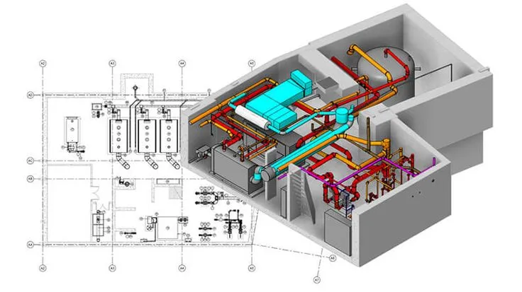
Structural & MEP Drawings
Now let’s shift from the architectural world to the backbone and bloodstream of a project. Structural drawings keep the building standing; MEP drawings keep it alive.
Structural Drawings
These sheets show the skeleton: footings, columns, beams, and slabs. Look for load paths where the weight starts and where it ends up. If something looks unsupported, check the next sheet before assuming. Structural notes also include rebar callouts, embed plates, and clearance dimensions that control spacing and cover.
Always verify grid alignment. A column off by even two inches can cause a chain reaction that affects walls, ceilings, and mechanical systems.
Mep Drawings
MEP means mechanical, electrical, and plumbing. These sheets are busy but vital.
- Mechanical shows ducts, diffusers, and equipment layouts.
- Electrical covers lighting plans, panels, conduit routing, and riser diagrams.
- Plumbing reveals pipe runs, slopes, and fixture locations.
You’ll also find panel and equipment schedules that tell you power load, size, and location. Coordination dimensions are your best friend here. They show how close systems can run before clashing.
Coordination Tip
When reviewing MEP with structural drawings, always bring up the gridlines. That’s your anchor. A duct or pipe that crosses a beam line might look fine on its own sheet, but clash in reality.
Every coordination meeting should trace the grid first, then trace the systems. That habit alone saves time, arguments, and more than a few dollars in rework.
Short Glossary Of Must-Know Terms
| Term | What It Means (in plain language) |
| Title Block | The information box on each sheet lists project name, drawing title, scale, date, author, and revision. It tells you what you’re looking at. |
| Revision Cloud | A hand-drawn loop or bubble marking changes made since the last issue. Always check these; they show what’s new. |
| Datum | A fixed reference point or level used to measure everything else from. It could be a floor height, a curb, or a survey benchmark. |
| O.C. (On Center) | The distance from the center of one element to the center of the next, like stud spacing or joist layout. |
| NTS (Not to Scale) | Tell you the drawing isn’t drawn at an exact proportion. Never measure from an NTS drawing; trust written dimensions only. |
| Riser | A vertical diagram that shows how pipes, ducts, or cables run between floors. Think of it as a vertical map. |
| Schedule | A chart that lists and describes components such as doors, windows, finishes, or lights. Tags on plans refer back to these lists. |
| BIM (Building Information Modeling) | A digital 3D model that combines architectural, structural, and MEP data for coordination and clash detection. |
| Coordination | The process of making sure all trades’ drawings fit together (structure, MEP, architecture) without conflicts. |
| As-Built | The final record drawings show how the project was actually constructed, including any field changes or deviations. |
Conclusion
Reading construction drawings isn’t magic. It’s a habit! One that is built through repetition, curiosity, and a sharp eye for detail. The best builders and site leads don’t rush through plans; they study them, question them, and cross-check before lifting a hammer. That’s how projects stay smooth, safe, and on budget.
Remember that small mistakes on paper turn into expensive fixes in the field. Studies have shown that rework and design deviations can eat up more than 12% of a project’s installed cost. Add in lost time and miscommunication, and industry losses climb into the hundreds of billions each year. That’s money, effort, and reputation, gone because someone missed a line or skipped a note.
So slow down. Read with intent. Treat every sheet like a conversation between the designer and the crew. Once you understand how to read drawings the right way, you won’t just build faster, you’ll build smarter. And that skill will follow you from one job to the next, long after the ink dries on the plans.


